Arduino Nano Controlled Robotic Vehicle with nRF24L01 Wireless Communication
Circuit Documentation
Summary
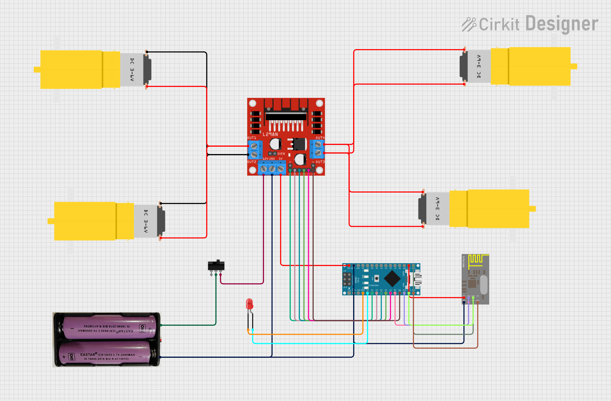
This circuit is designed to control a set of four "Motor amarillo motorreductor hobby" motors using an L298N DC motor driver module. The system is controlled by an Arduino Nano microcontroller, which interfaces with an nRF24L01 wireless transceiver module for remote control capabilities. A toggle switch is used to control the power supply to the motor driver, and a red LED is included for status indication. The power source for the circuit is a 7.4V battery.
Component List
Motors
- Motor amarillo motorreductor hobby: A hobbyist DC gear motor used for driving mechanical loads.
Microcontroller
- Arduino Nano: A small, complete, and breadboard-friendly board based on the ATmega328P, used for controlling the logic of the circuit.
Power
- 7.4V Battery: Provides the power supply for the motors and the motor driver module.
Motor Driver
- L298N DC Motor Driver: An integrated circuit that allows for controlling the speed and direction of two DC motors simultaneously.
Wireless Module
- nRF24L01: A wireless transceiver module that operates in the 2.4GHz band, used for receiving control signals.
Indicator
- LED: Two Pin (red): An indicator light that can be used to signal various statuses of the circuit.
Switch
- Toggle Switch: A switch that can be used to turn the power supply to the motor driver on or off.
Wiring Details
Motors
- Motor amarillo motorreductor hobby: Each motor has two connections,
vccandGND. Thevccof two motors are connected toOUT4andOUT3of the L298N motor driver, while theGNDof the same two motors are connected toOUT2andOUT1respectively.
Arduino Nano
- Digital pins
D2toD7are used to control the L298N motor driver and the nRF24L01 module. VINis connected to the5Vpin of the L298N motor driver to power the Arduino Nano.GNDis connected to the common ground of the circuit.3V3powers the nRF24L01 module.D13/SCK,D11/MOSI, andD12/MISOare used for SPI communication with the nRF24L01 module.
L298N DC Motor Driver
OUT1,OUT2,OUT3, andOUT4are connected to the motors.ENAandENBare connected toD3andD9on the Arduino Nano for enabling the motor outputs.IN1,IN2,IN3, andIN4are connected toD4,D5,D6, andD7on the Arduino Nano for controlling motor direction.12Vis connected to theL2pin of the toggle switch to control power to the motors.GNDis connected to the common ground of the circuit.
nRF24L01
VCCis connected to3V3on the Arduino Nano.GNDis connected to the common ground of the circuit.CE,CSN,SCK,MOSI, andMISOare connected toD8,D10,D13/SCK,D11/MOSI, andD12/MISOon the Arduino Nano respectively.
LED: Two Pin (red)
cathodeis connected toGNDon the Arduino Nano.anodeis connected toD2on the Arduino Nano.
Toggle Switch
COMis connected to the positive terminal of the 7.4V battery.L2is connected to the12Vinput of the L298N motor driver.
Documented Code
Arduino Nano Code
#include<SPI.h>
#include<nRF24L01.h>
#include<RF24.h>

int ENA = 3;
int ENB = 9;
int MotorA1 = 4;
int MotorA2 = 5;
int MotorB1 = 6;
int MotorB2 = 7;

RF24 radio(8, 10);

const byte address[6] = "00001";

struct data {
  int xAxis;
  int yAxis;
};
data receive_data;

void setup() {
  Serial.begin(9600);
  radio.begin();
  radio.openReadingPipe(0,address);
  radio.setPALevel(RF24_PA_MIN);
  radio.setDataRate(RF24_250KBPS);
  radio.startListening();
  pinMode(ENA, OUTPUT);
  pinMode(ENB, OUTPUT);
  pinMode(MotorA1, OUTPUT);
  pinMode(MotorA2, OUTPUT);
  pinMode(MotorB1, OUTPUT);
  pinMode(MotorB2, OUTPUT);
}

void loop() {
  while(radio.available()) {
    radio.read(&receive_data, sizeof(data));
    if(receive_data.yAxis > 400) {
      digitalWrite(MotorA1, LOW);
      digitalWrite(MotorA2, HIGH);
      digitalWrite(MotorB1, HIGH);
      digitalWrite(MotorB2, LOW);
      analogWrite(ENA, 150);
      analogWrite(ENB, 150);
    } else if(receive_data.yAxis < 320) {
      digitalWrite(MotorA1, HIGH);
      digitalWrite(MotorA2, LOW);
      digitalWrite(MotorB1, LOW);
      digitalWrite(MotorB2, HIGH);
      analogWrite(ENA, 150);
      analogWrite(ENB, 150);
    } else if(receive_data.xAxis < 320){
      digitalWrite(MotorA1, HIGH);
      digitalWrite(MotorA2, LOW);
      digitalWrite(MotorB1, HIGH);
      digitalWrite(MotorB2, LOW);
      analogWrite(ENA, 150);
      analogWrite(ENB, 150);
    } else if(receive_data.xAxis > 400){
      digitalWrite(MotorA1, LOW);
      digitalWrite(MotorA2, HIGH);
      digitalWrite(MotorB1, LOW);
      digitalWrite(MotorB2, HIGH);
      analogWrite(ENA, 150);
      analogWrite(ENB, 150);
    } else {
      digitalWrite(MotorA1, LOW);
      digitalWrite(MotorA2, LOW);
      digitalWrite(MotorB1, LOW);
      digitalWrite(MotorB2, LOW);
      analogWrite(ENA, 0);
      analogWrite(ENB, 0);
    }
  }
}
This code is responsible for setting up the Arduino Nano to communicate with the nRF24L01 module and control the L298N motor driver based on the received wireless signals. It initializes the SPI communication, sets up the radio, and configures the motor control pins. The loop function listens for incoming data and controls the motors accordingly.