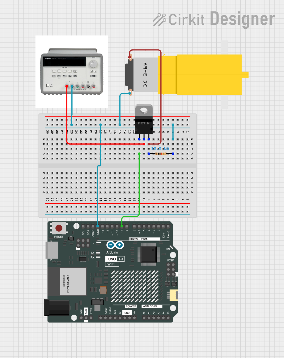
Arduino-Controlled Motor with MOSFET and Power Supply

Circuit Documentation
Summary of the Circuit
This circuit appears to be designed to control a motor using an Arduino UNO R4 WiFi microcontroller. The motor's power is controlled through an nMOS transistor, which acts as a switch. The gate of the MOSFET is driven by one of the digital pins (D9) of the Arduino, allowing the microcontroller to turn the motor on and off. A resistor is used to pull the gate to a known state when the microcontroller is not actively driving it. The power for the motor is supplied by a Triple Output DC Power Supply, which also provides the ground reference for the entire circuit.
Component List
Arduino UNO R4 WiFi
- Microcontroller board with WiFi capability.
- It has a variety of digital and analog pins for interfacing with various sensors, actuators, and other electronic components.
Triple Output DC Power Supply
- Provides multiple voltage outputs, including a 6V supply used in this circuit.
- It has a common ground and can supply power for various components.
Motor Amarillo Motorreductor Hobby
- A small hobby motor that operates on a DC voltage.
- It has two terminals: one for the power supply (Vcc) and one for the ground (GND).
nMOS Transistor (MOSFET)
- Acts as an electronic switch to control the flow of current to the motor.
- It has three terminals: gate (control signal), drain (connected to the motor), and source (connected to the ground).
Resistor
- A 10k Ohm resistor used to pull the gate of the MOSFET to a known state.
Wiring Details
Arduino UNO R4 WiFi
- GND: Connected to the ground net, which includes the ground of the motor, the source of the MOSFET, and the negative terminal of the power supply.
- D9: Connected to the gate of the nMOS transistor to control the motor.
Triple Output DC Power Supply
- 6V +: Connected to the drain of the nMOS transistor, providing power to the motor when the transistor is on.
- 6V -: Connected to the ground net, serving as the common ground for the circuit.
Motor Amarillo Motorreductor Hobby
- Vcc: Connected to the source of the nMOS transistor, which will be connected to the power supply when the transistor is on.
- GND: Connected to the ground net.
nMOS Transistor (MOSFET)
- Gate: Connected to the D9 pin of the Arduino UNO R4 WiFi to receive the control signal.
- Drain: Connected to the positive terminal (6V +) of the power supply.
- Source: Connected to the ground net.
Resistor
- Pin1: Connected to the source of the nMOS transistor and the ground net.
- Pin2: Connected to the gate of the nMOS transistor to ensure it is pulled to a known state when not driven by the Arduino.
Documented Code
void setup() {
  // Initialize digital pin D9 as an output.
  pinMode(9, OUTPUT);
}

void loop() {
  // Turn the motor on by setting D9 high.
  digitalWrite(9, HIGH);
  delay(1000); // Wait for 1 second.

  // Turn the motor off by setting D9 low.
  digitalWrite(9, LOW);
  delay(1000); // Wait for 1 second.
}
This code snippet is a simple example of how to control the motor using the Arduino. The setup() function configures pin D9 as an output. The loop() function then repeatedly turns the motor on and off by setting D9 high and low, respectively, with a one-second delay between each state change.