Cirkit Designer
Your all-in-one circuit design IDE
Home /
Project Documentation
ESP32-Controlled Stepper and Servo Motor System with A4988 Driver and Micro Switch Feedback
Circuit Documentation
Summary
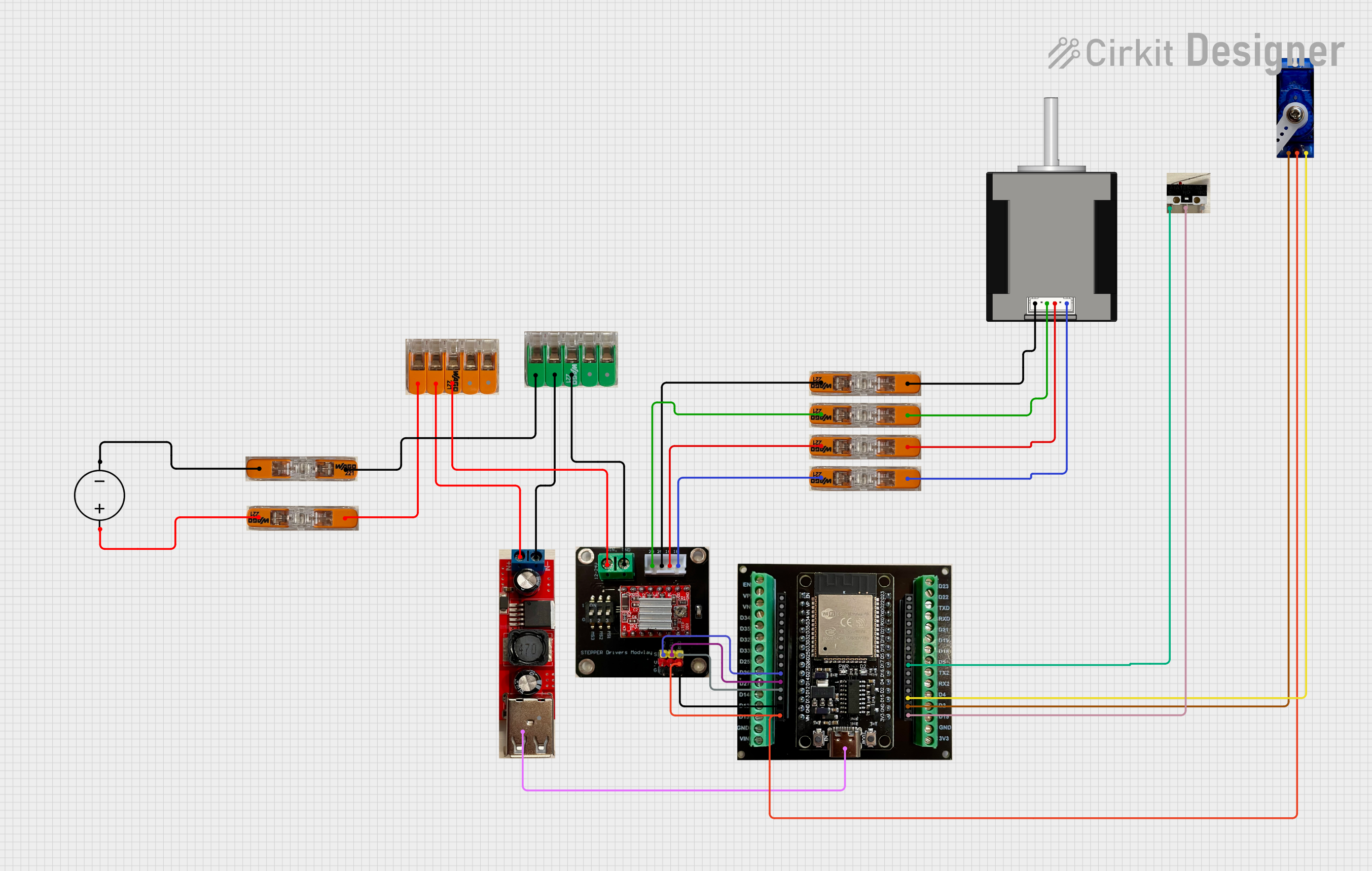
This circuit is designed to control a stepper motor using an A4988 stepper motor driver and an ESP32 microcontroller. Additionally, the circuit includes a servo motor, a micro switch, and a step-down converter USB for power regulation. The power source for the circuit is a DC power supply. WAGO connectors are used throughout the circuit for reliable and easy connections.
Component List
A4988 on Breakout Board
- Stepper motor driver that allows control of one bipolar stepper motor.
- Pins: VIN (12-24V), GND, 2B, 2A, 1A, 1B, ENABLE, STEP, DIR, VDD (5V).
WAGO Connectors
- Terminal block connectors used for making secure and easy wire connections.
- Pins: AWG 18-14.
Nema 17 42-STH48
- A bipolar stepper motor commonly used for precision control in CNC machines and 3D printers.
- Pins: A2 (black), A1 (green), B2 (red), B1 (blue).
ESP32 (30 PIN) on Breakout Board
- A powerful microcontroller with Wi-Fi and Bluetooth capabilities.
- Pins: 3V3, GND, D15, D2, D4, D16, D17, D5, D18, D19, D21, RX0, TX0, D22, D23, EN, VP, VN, D34, D35, D32, D33, D25, D26, D27, D14, D12, D13, VIN, USB-C.
Step Down Converter USB (12-24V)
- A power converter that steps down voltage to a USB output.
- Pins: IN+ (6-40V), IN- (6-40V), USB (2/2), USB (1/2).
Servo Motor
- A rotary actuator that allows for precise control of angular position.
- Pins: GND, VDD (5V).
Micro Switch
- An electric switch that is actuated by very little physical force.
- Pins: NC, C, NO.
DC Power Source
- Provides the electrical power to the circuit.
- Pins: Ground, Positive.
Wiring Details
A4988 on Breakout Board
- VIN (12-24V) connected to WAGO Connector 5-conductor.
- GND connected to WAGO Connector Green 5-conductor.
- 2B connected to WAGO Connector.
- 2A connected to WAGO Connector.
- 1A connected to WAGO Connector.
- 1B connected to WAGO Connector.
- ENABLE connected to ESP32 (D27).
- STEP connected to ESP32 (D14).
- DIR connected to ESP32 (D12).
- VDD (5V) connected to ESP32 (VIN) and Servo Motor (VDD).
WAGO Connectors
- Various connections to A4988, ESP32, Nema 17, DC Power Source, and Step Down Converter.
Nema 17 42-STH48
- A2 (black) connected to WAGO Connector.
- A1 (green) connected to WAGO Connector.
- B2 (red) connected to WAGO Connector.
- B1 (blue) connected to WAGO Connector.
ESP32 (30 PIN) on Breakout Board
- 3V3 connected to Micro Switch (C).
- GND connected to A4988 (GND) and Servo Motor (GND).
- D15 connected to Servo Motor.
- D17 connected to Micro Switch (NC).
- D27 connected to A4988 (ENABLE).
- D14 connected to A4988 (STEP).
- D12 connected to A4988 (DIR).
- VIN connected to Servo Motor (VDD) and A4988 (VDD).
- USB-C connected to Step Down Converter USB.
Step Down Converter USB (12-24V)
- IN+ (6-40V) connected to WAGO Connector 5-conductor.
- IN- (6-40V) connected to WAGO Connector Green 5-conductor.
Servo Motor
- VDD (5V) connected to ESP32 (VIN).
- GND connected to ESP32 (GND).
Micro Switch
- NC connected to ESP32 (D17).
- C connected to ESP32 (3V3).
DC Power Source
- Positive connected to WAGO Connector.
- Ground connected to WAGO Connector.
Documented Code
# stepper_motor.yaml
esphome:
  name: stepper-motor
  friendly_name: stepper_motor

esp32:
  board: esp32dev
  framework:
    type: arduino

# Enable logging
logger:

# Enable Home Assistant API
api:
  encryption:
    key: "xyz"

ota:
  - platform: esphome
    password: "xyz"

wifi:
  ssid: xyz
  password: xyz
  # Enable fallback hotspot (captive portal) in case wifi connection fails
  ap:
    ssid: "Stepper-Motor Fallback Hotspot"
    password: "xyz"

captive_portal:

# Controlling the stepper motor for door opening and closing
stepper:
  - platform: a4988
    id: my_stepper
    dir_pin: GPIO12 # "D12" on ESP32
    step_pin: GPIO14 # "D14" on ESP32
    max_speed: 250 steps/s # 1-250 steps/s
    # sleep_pin: GPIO13
    acceleration: 100  # 1 bis inf
    deceleration: 50  # 1 bis inf

# Controlling the servo motor for window/door shutter
servo:
  - id: servo1
    output: output1

output:
  - platform: ledc # For ESP8266 use: esp8266_pwm
    id: output1
    pin: GPIO15
    frequency: 50 Hz # MUST BE 50Hz

# For Dashboard
number:
  - platform: template
    name: Stepper Control
    min_value: -150     #-100
    max_value: 150   #100
    step: 1
    set_action:
      then:
        - stepper.set_target:
            id: my_stepper
            target: !lambda 'return x;'    # target: !lambda 'return x*10;'
  - platform: template
    name: Servo Control
    icon: mdi:sync
    optimistic: true
    min_value: -100
    max_value: 100
    initial_value: 0
    step: 5
    on_value:
      then:
        - lambda: !lambda |-
            // Servo Write range is: -1.0 to 1.0, so divide by 100
            id(servo1).write(x / 100.0);

# One PIN is used to turn on (enable) the stepper motor driver
switch:
  - platform: gpio
    pin: GPIO27
    inverted: true
    id: switch_motor_door
    name: "Stepper Motor Enabler"

# Input for micro switch as a sensor for a completely open door
binary_sensor:
  - platform: gpio
    pin:
      number: GPIO17
      mode: INPUT_PULLDOWN
    name: "Door completely open"
    id: door_completely_open
This code is designed to run on an ESP32 microcontroller and is written using the ESPHome framework. It includes configurations for controlling a stepper motor and a servo motor, connecting to Wi-Fi, and setting up a fallback hotspot. It also includes a binary sensor for a micro switch and a switch to enable the stepper motor driver.