
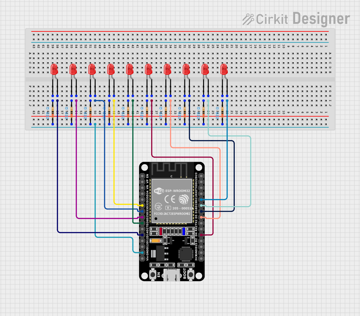
Circuit Documentation
Summary
This circuit consists of an ESP32 microcontroller controlling ten red LEDs through GPIO pins. Each LED is connected in series with a 220 Ohm resistor to limit the current. The microcontroller is programmed to light up the LEDs in a specific pattern.
Component List
ESP32 (30 pin)
- Description: A powerful microcontroller with built-in Wi-Fi and Bluetooth capabilities.
- Pins: EN, VP, VN, D34, D35, D32, D33, D25, D26, D27, D14, D12, D13, GND, Vin, D23, D22, TX0, RX0, D21, D19, D18, D5, TX2, RX2, D4, D2, D15, 3V3
LED: Two Pin (red)
- Description: A standard red LED with two pins: anode and cathode.
- Pins: cathode, anode
Resistor
- Description: A 220 Ohm resistor used to limit the current through the LEDs.
- Pins: pin1, pin2
- Properties:
- Resistance: 220 Ohms
Wiring Details
ESP32 (30 pin)
- D21 connected to anode of LED 1
- D19 connected to anode of LED 2
- D18 connected to anode of LED 3
- D5 connected to anode of LED 4
- D4 connected to anode of LED 5
- D26 connected to anode of LED 6
- D32 connected to anode of LED 7
- D33 connected to anode of LED 8
- D25 connected to anode of LED 9
- D14 connected to anode of LED 10
- GND connected to pin1 of all resistors
LED: Two Pin (red)
LED 1:
- anode connected to D21 of ESP32
- cathode connected to pin2 of Resistor 1
LED 2:
- anode connected to D19 of ESP32
- cathode connected to pin2 of Resistor 2
LED 3:
- anode connected to D18 of ESP32
- cathode connected to pin2 of Resistor 3
LED 4:
- anode connected to D5 of ESP32
- cathode connected to pin2 of Resistor 4
LED 5:
- anode connected to D4 of ESP32
- cathode connected to pin2 of Resistor 5
LED 6:
- anode connected to D26 of ESP32
- cathode connected to pin2 of Resistor 6
LED 7:
- anode connected to D32 of ESP32
- cathode connected to pin2 of Resistor 7
LED 8:
- anode connected to D33 of ESP32
- cathode connected to pin2 of Resistor 8
LED 9:
- anode connected to D25 of ESP32
- cathode connected to pin2 of Resistor 9
LED 10:
- anode connected to D14 of ESP32
- cathode connected to pin2 of Resistor 10
Resistor
Resistor 1:
- pin1 connected to GND of ESP32
- pin2 connected to cathode of LED 1
Resistor 2:
- pin1 connected to GND of ESP32
- pin2 connected to cathode of LED 2
Resistor 3:
- pin1 connected to GND of ESP32
- pin2 connected to cathode of LED 3
Resistor 4:
- pin1 connected to GND of ESP32
- pin2 connected to cathode of LED 4
Resistor 5:
- pin1 connected to GND of ESP32
- pin2 connected to cathode of LED 5
Resistor 6:
- pin1 connected to GND of ESP32
- pin2 connected to cathode of LED 6
Resistor 7:
- pin1 connected to GND of ESP32
- pin2 connected to cathode of LED 7
Resistor 8:
- pin1 connected to GND of ESP32
- pin2 connected to cathode of LED 8
Resistor 9:
- pin1 connected to GND of ESP32
- pin2 connected to cathode of LED 9
Resistor 10:
- pin1 connected to GND of ESP32
- pin2 connected to cathode of LED 10
Code Documentation
int L1 = 14;
int L2 = 25;
int L3 = 33;
int L4 = 32;
int L5 = 26;
int L6 = 4;
int L7 = 5;
int L8 = 18;
int L9 = 19;
int L10 = 21;

void setup() {
  pinMode(L1, OUTPUT);
  pinMode(L2, OUTPUT);
  pinMode(L3, OUTPUT);
  pinMode(L4, OUTPUT);
  pinMode(L5, OUTPUT);
  pinMode(L6, OUTPUT);
  pinMode(L7, OUTPUT);
  pinMode(L8, OUTPUT);
  pinMode(L9, OUTPUT);
  pinMode(L10, OUTPUT);
}

void loop(){
  //pattern 1
  digitalWrite(L1, HIGH);
  delay(200);
  digitalWrite(L2, HIGH);
  delay(200);
  digitalWrite(L3, HIGH);
  delay(200);
  digitalWrite(L4, HIGH);
  delay(200);
  digitalWrite(L5, HIGH);
  delay(200);
  digitalWrite(L6, HIGH);
  delay(200);
  digitalWrite(L7, HIGH);
  delay(200);
  digitalWrite(L8, HIGH);
  delay(200);
  digitalWrite(L9, HIGH);
  delay(200);
  digitalWrite(L10, HIGH);
  delay(1000);

  // pattern 2
  digitalWrite(L1, LOW);
  delay(200);
  digitalWrite(L2, LOW);
  delay(200);
  digitalWrite(L3, LOW);
  delay(200);
  digitalWrite(L4, LOW);
  delay(200);
  digitalWrite(L5, LOW);
  delay(200);
  digitalWrite(L6, LOW);
  delay(200);
  digitalWrite(L7, LOW);
  delay(200);
  digitalWrite(L8, LOW);
  delay(200);
  digitalWrite(L9, LOW);
  delay(200);
  digitalWrite(L10, LOW);
  delay(1000);
}
This code sets up the GPIO pins connected to the LEDs as outputs and then runs a loop that lights up the LEDs in a sequence with a delay between each LED turning on and off.