
Arduino Mega 2560-Based Battery-Powered BLDC Motor Control System with NRF24L01 Wireless Communication
View and Edit Project In Cirkit Designer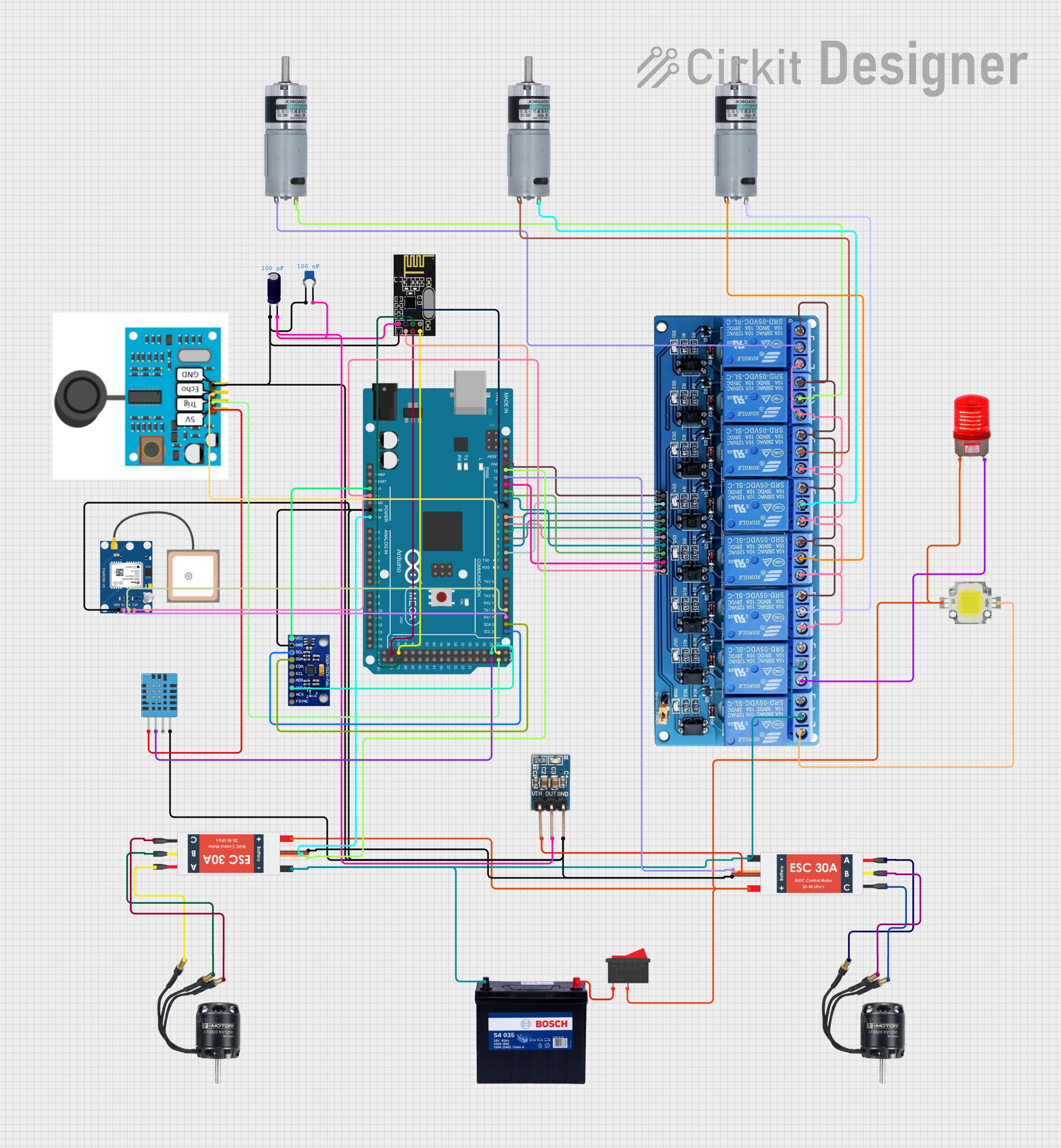
Circuit Documentation
Summary
This document provides a detailed overview of a circuit design that includes various components such as an NRF24L01 wireless module, a 12V 200Ah battery, electronic speed controllers (ESCs), a rocker switch, capacitors, BLDC motors, sensors, an Arduino Mega 2560, and other components. The circuit is designed to interface these components to achieve a specific functionality, which is controlled by the Arduino Mega 2560 microcontroller.
Component List
NRF24L01
- Description: Wireless communication module
- Pins: IRQ (not used), MOSI, CSN, VCC (3V), GND, CE, SCK, MISO
12V 200Ah Battery
- Description: Power source
- Pins: GND, 12V
Electronic Speed Controller (ESC)
- Description: Controls the speed of BLDC motors
- Pins: Battery VCC, Battery GND, Signal, 5V out, GND out, M1, M2, M3
Rocker Switch
- Description: On/Off switch
- Pins: 1, 2
Electrolytic Capacitor
- Description: Capacitor with 0.0001 Farads capacitance
- Pins: -, +
Ceramic Capacitor
- Description: Capacitor with 0.0000001 Farads capacitance
- Pins: pin0, pin1
BLDC Motor
- Description: Brushless DC motor
- Pins: Wire A, Wire B, Wire C
DHT11 Humidity and Temperature Sensor
- Description: Sensor for measuring humidity and temperature
- Pins: VDD, DATA, NULL, GND
JSN-SR04T Sensor
- Description: Ultrasonic distance sensor
- Pins: 5V, TRIG, ECHO, GND
Red Light 220VAC
- Description: Indicator light
- Pins: -, +
Power LED 12V 10W 0.8-0.9A
- Description: High-power LED
- Pins: +, -
MRB Planetary Gearbox Motor
- Description: Motor with planetary gearbox
- Pins: +, -
3.3V Regulator
- Description: Voltage regulator
- Pins: GND, OUT, Vin
GPS NEO 6M
- Description: GPS module
- Pins: VCC, RX, TX, GND
Arduino Mega 2560
- Description: Microcontroller board
- Pins: IOREF, RESET, 3V3, 5V, GND, VIN, A0-A15, D0-D53, AREF, SDA, SCL
5V 8-Channel Relay
- Description: Relay module
- Pins: GND, IN1-IN8, VCC, NC, C, NO
MPU-9250/6500/9255
- Description: 9-axis motion tracking device
- Pins: VCC, GND, SCL/SCLK, SDA/SDI, EDA, ECL, ADO/SDO, INT, NCS, FSYNC
Wiring Details
NRF24L01
- MOSI connected to Arduino Mega 2560 D51
- CSN connected to Arduino Mega 2560 D8 PWM
- VCC (3V) connected to Electrolytic Capacitor +, 3.3V Regulator OUT, Ceramic Capacitor pin1
- GND connected to JSN-SR04T Sensor GND, Electrolytic Capacitor -, MPU-9250/6500/9255 GND, Arduino Mega 2560 GND, Electronic Speed Controller (ESC) GND out, 3.3V Regulator GND, GPS NEO 6M GND, Ceramic Capacitor pin0, DHT11 Humidity and Temperature Sensor GND
- CE connected to Arduino Mega 2560 D7 PWM
- SCK connected to Arduino Mega 2560 D52
- MISO connected to Arduino Mega 2560 D50
12V 200Ah Battery
- GND connected to 5V 8-Channel Relay C, Electronic Speed Controller (ESC) Battery GND
- 12V connected to Rocker Switch 1
Electronic Speed Controller (ESC)
- Battery VCC connected to Power LED 12V 10W 0.8-0.9A +, Red Light 220VAC +, Rocker Switch 2
- Battery GND connected to 12V 200Ah Battery GND
- Signal connected to Arduino Mega 2560 D13 PWM
- 5V out connected to Arduino Mega 2560 VIN, 3.3V Regulator Vin
- GND out connected to Common GND
- M1 connected to BLDC Motor Wire A
- M2 connected to BLDC Motor Wire B
- M3 connected to BLDC Motor Wire C
Rocker Switch
- 1 connected to 12V 200Ah Battery 12V
- 2 connected to Electronic Speed Controller (ESC) Battery VCC
Electrolytic Capacitor
- + connected to NRF24L01 VCC (3V)
- - connected to Common GND
Ceramic Capacitor
- pin0 connected to Common GND
- pin1 connected to NRF24L01 VCC (3V)
BLDC Motor
- Wire A connected to Electronic Speed Controller (ESC) M1
- Wire B connected to Electronic Speed Controller (ESC) M2
- Wire C connected to Electronic Speed Controller (ESC) M3
DHT11 Humidity and Temperature Sensor
- VDD connected to JSN-SR04T Sensor 5V
- DATA connected to Arduino Mega 2560 D25
- GND connected to Common GND
JSN-SR04T Sensor
- 5V connected to DHT11 Humidity and Temperature Sensor VDD
- TRIG connected to Arduino Mega 2560 D23
- ECHO connected to Arduino Mega 2560 D22
- GND connected to Common GND
Red Light 220VAC
- + connected to Electronic Speed Controller (ESC) Battery VCC
- - connected to 5V 8-Channel Relay NO
Power LED 12V 10W 0.8-0.9A
- + connected to Electronic Speed Controller (ESC) Battery VCC
- - connected to 5V 8-Channel Relay NO
MRB Planetary Gearbox Motor
- + connected to 5V 8-Channel Relay C
- - connected to 5V 8-Channel Relay C
3.3V Regulator
- GND connected to Common GND
- OUT connected to NRF24L01 VCC (3V)
- Vin connected to Electronic Speed Controller (ESC) 5V out
GPS NEO 6M
- VCC connected to 5V 8-Channel Relay VCC
- RX connected to Arduino Mega 2560 D18/TX1
- TX connected to Arduino Mega 2560 D19/RX1
- GND connected to Common GND
Arduino Mega 2560
- D51 connected to NRF24L01 MOSI
- D8 PWM connected to NRF24L01 CSN
- GND connected to Common GND
- D7 PWM connected to NRF24L01 CE
- D52 connected to NRF24L01 SCK
- D50 connected to NRF24L01 MISO
- D13 PWM connected to Electronic Speed Controller (ESC) Signal
- VIN connected to Electronic Speed Controller (ESC) 5V out
- D25 connected to DHT11 Humidity and Temperature Sensor DATA
- D23 connected to JSN-SR04T Sensor TRIG
- D22 connected to JSN-SR04T Sensor ECHO
- D18/TX1 connected to GPS NEO 6M RX
- D19/RX1 connected to GPS NEO 6M TX
- 3V3 connected to MPU-9250/6500/9255 VCC
- D21/SCL connected to MPU-9250/6500/9255 SCL/SCLK
- D20/SDA connected to **MPU-9250/