
Arduino-Controlled Stepper Motor with A4988 Driver and Speed Control
View and Edit Project In Cirkit Designer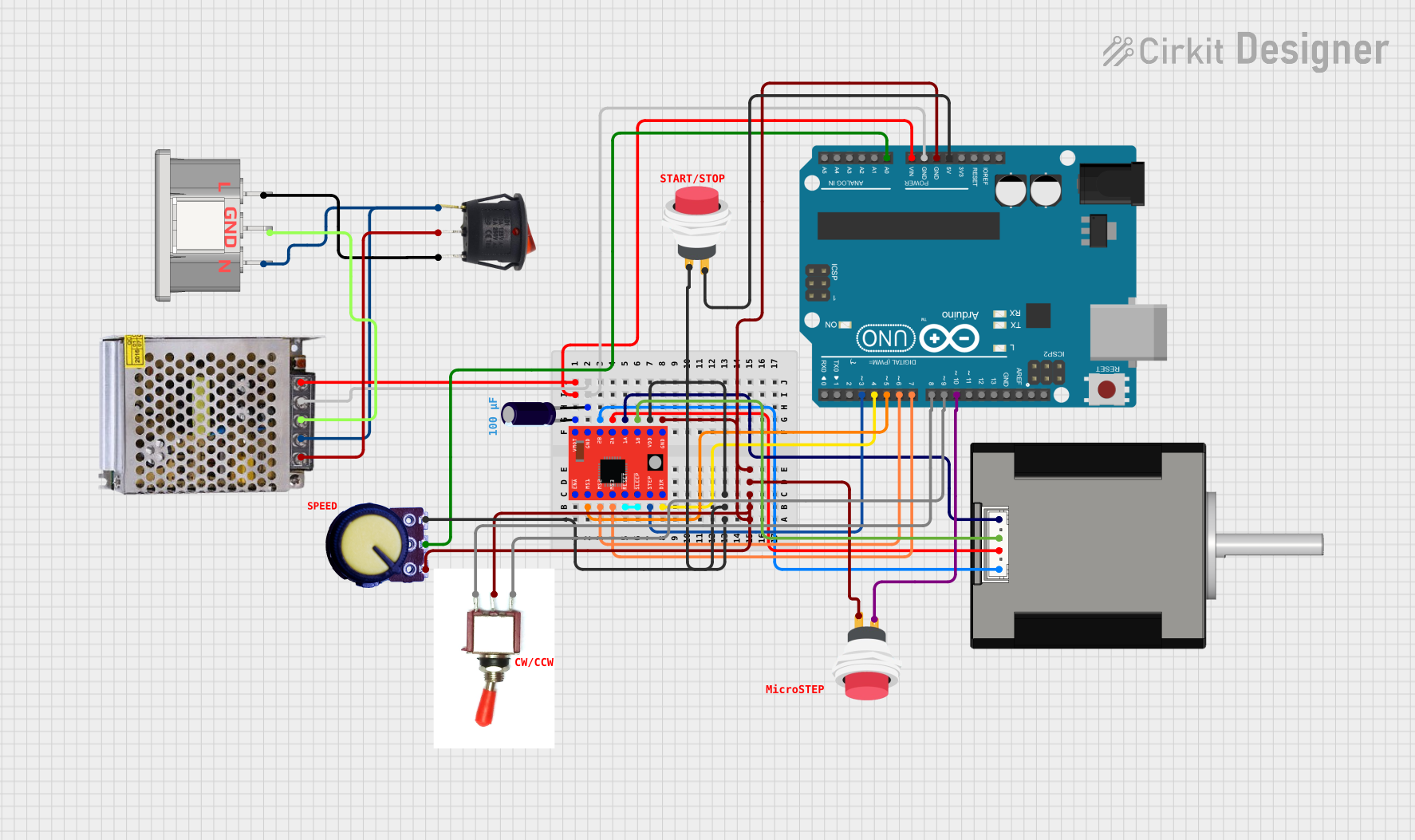
Circuit Documentation
Summary
This circuit is designed to control a Nema 17 stepper motor using an A4988 stepper motor driver. The motor's speed and direction are adjustable via a potentiometer and a toggle switch, respectively. The circuit is powered by a 12V 5A power supply, which is switched on and off using a round rocker switch. The Arduino UNO microcontroller is used to generate the control signals for the A4988 driver based on the inputs from the potentiometer and toggle switch.
Component List
Arduino UNO
- Microcontroller board based on the ATmega328P
- Provides I/O pins for interfacing with various components
POWER SUPPLY 12V 5AMP
- Provides a 12V DC output from a 220V AC input
- Powers the circuit including the Arduino UNO and the A4988 driver
Round Rocker Switch
- Acts as an on/off switch for the power supply
A4988 Stepper Motor Driver (Red)
- Drives the stepper motor based on signals from the Arduino UNO
- Configurable micro-stepping resolution
Electrolytic Capacitor
- Stabilizes the voltage supply to the A4988 driver
IEC320 In
- AC power input connector
2Pin Push Switch (x2)
- Momentary push switches used for input control
Toggle Switch
- Changes the direction of the stepper motor
Potentiometer
- Adjusts the speed of the stepper motor
Nema 17 42-STH48
- A stepper motor controlled by the A4988 driver
Wiring Details
Arduino UNO
Vinconnected to the 12V output of the power supplyGNDconnected to the ground of the power supply and the A4988 driverD3(stepPin) connected to theSTEPpin of the A4988 driverD4(dirPin) connected to theDIRpin of the A4988 driverD5(ms1Pin) connected to theMS1pin of the A4988 driverD6(ms2Pin) connected to theMS2pin of the A4988 driverD7(ms3Pin) connected to theMS3pin of the A4988 driverD8connected to theGndpin of the Toggle SwitchD9(toggleSwitchL1) connected to theVccpin of the Toggle SwitchD10(rockerSwitchInput) connected to one of the 2Pin Push SwitchesA0(potPin) connected to theOutputpin of the Potentiometer5Vconnected to the other 2Pin Push Switch
POWER SUPPLY 12V 5AMP
220V Positive Pole (AC)connected to theInput +of the Round Rocker Switch220V Negative Pole (AC)connected to theNof the IEC320 InGND (DC)connected to the ground of the circuit12V-24V Output (DC)connected to theVinof the Arduino UNO and theVMOTof the A4988 driver
Round Rocker Switch
Input +connected to the220V Positive Pole (AC)of the power supplyGroundconnected to theGNDof the IEC320 InOutput +connected to theLof the IEC320 In
A4988 Stepper Motor Driver (Red)
VMOTconnected to the 12V output of the power supplyGNDconnected to the ground of the power supply and the Arduino UNOMS1,MS2,MS3connected toD5,D6,D7of the Arduino UNO respectivelyRESETandSLEEPpins are shorted togetherSTEPconnected toD3of the Arduino UNODIRconnected toD4of the Arduino UNOVDDconnected to theVCCpin of the Potentiometer1A,1B,2A,2Bconnected to the corresponding pins of the Nema 17 stepper motor
Electrolytic Capacitor
+connected to theVMOTof the A4988 driver-connected to the ground of the circuit
IEC320 In
Lconnected to theOutput +of the Round Rocker SwitchGNDconnected to the ground of the circuitNconnected to the220V Negative Pole (AC)of the power supply
2Pin Push Switch
- One switch has
Input +connected to5Vof the Arduino UNO andOutput +connected to theVDDof the A4988 driver - The other switch has
Input +connected toD10of the Arduino UNO
Toggle Switch
Vccconnected toD9of the Arduino UNOSigconnected to the ground of the circuitGndconnected toD8of the Arduino UNO
Potentiometer
VCCconnected to theVDDof the A4988 driverOutputconnected toA0of the Arduino UNOGNDconnected to the ground of the circuit
Nema 17 42-STH48
A1 GreenandA2 (black)connected to1Band1Aof the A4988 driver respectivelyB1 BlueandB2 Redconnected to2Band2Aof the A4988 driver respectively
Documented Code
/*
 * Arduino Sketch for Stepper Motor Control
 * This code controls a stepper motor using an A4988 driver.
 * The motor's speed and direction can be controlled via a potentiometer and toggle switch.
 * The rocker switch is used to power the circuit.
 */

// Pin definitions
const int stepPin = 3;
const int dirPin = 4;
const int ms1Pin = 5;
const int ms2Pin = 6;
const int ms3Pin = 7;
const int enablePin = 8;
const int toggleSwitchL1 = 9;
const int rockerSwitchInput = 10;
const int potPin = A0;

void setup() {
  // Set pin modes
  pinMode(stepPin, OUTPUT);
  pinMode(dirPin, OUTPUT);
  pinMode(ms1Pin, OUTPUT);
  pinMode(ms2Pin, OUTPUT);
  pinMode(ms3Pin, OUTPUT);
  pinMode(enablePin, OUTPUT);
  pinMode(toggleSwitchL1, INPUT);
  pinMode(rockerSwitchInput, INPUT);
  pinMode(potPin, INPUT);

  // Initialize pins
  digitalWrite(enablePin, LOW); // Enable the driver
  digitalWrite(ms1Pin, LOW); // Full step mode
  digitalWrite(ms2Pin, LOW); // Full step mode
  digitalWrite(ms3Pin, LOW); // Full step mode
}

void loop() {
  // Read the potentiometer value
  int potValue = analogRead(potPin);
  // Map the potentiometer value to a delay time
  int delayTime = map(potValue, 0, 1023, 1000, 200);

  // Read the toggle switch state
  int toggleState = digitalRead(toggleSwitchL1);
  // Set the direction based on the toggle switch state
  digitalWrite(dirPin, toggleState);

  // Step the motor
  digitalWrite(stepPin, HIGH);
  delayMicroseconds(delayTime);
  digitalWrite(stepPin, LOW);
  delayMicroseconds(delayTime);
}
This code is designed to run on an Arduino UNO and controls the A4988 stepper motor driver to operate the stepper motor. The speed of the motor is determined by the value read from the potentiometer, and the direction is controlled by the state of the toggle switch. The code sets up the necessary pins as inputs or outputs and initializes the driver in full step mode. The main loop reads the potentiometer value, maps it to a delay time, reads the toggle switch state to set the direction, and then steps the motor accordingly.