Wi-Fi Controlled Smart Lighting System with ESP8266 and Relay Module
Circuit Documentation
Summary of the Circuit
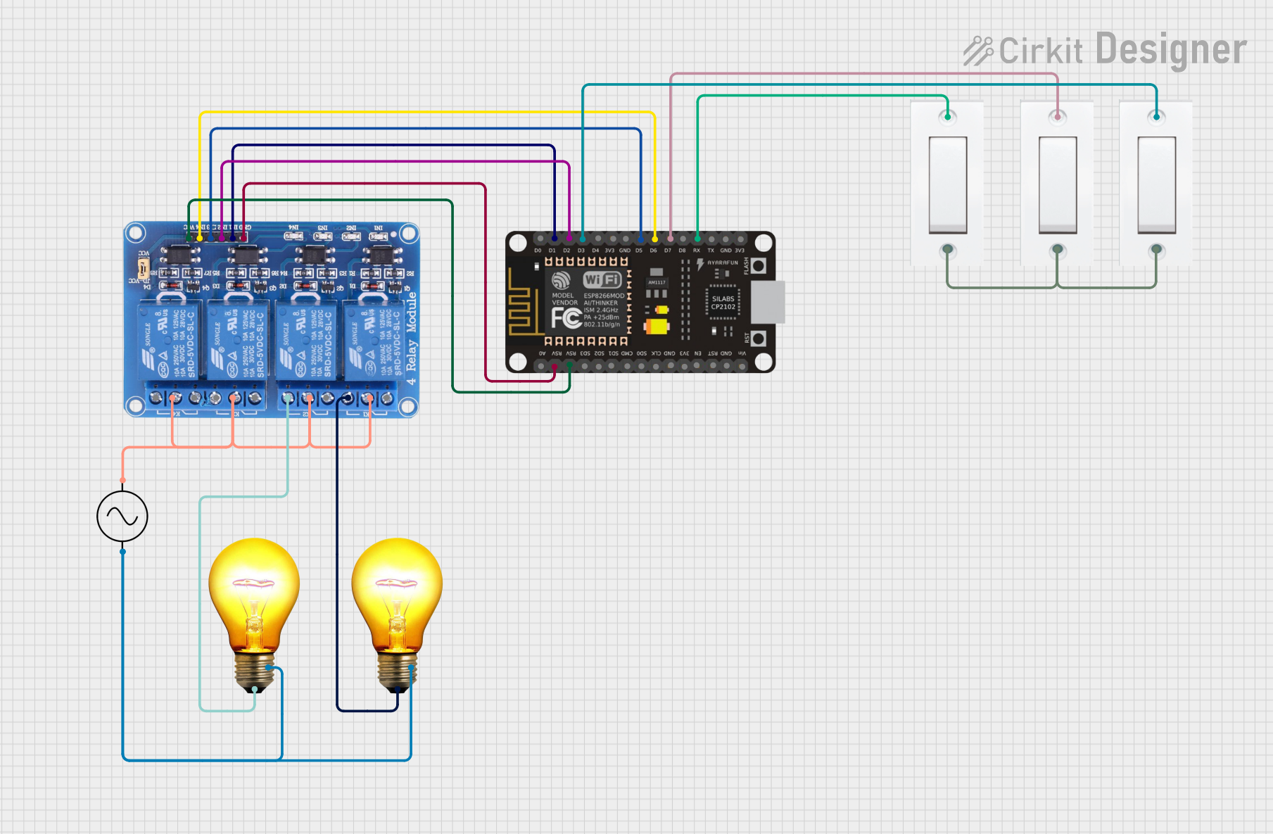
This circuit is designed to control multiple AC bulbs using a 4-channel relay module, which is interfaced with an ESP8266 NodeMCU microcontroller. The relay module allows for the independent control of each bulb, enabling the microcontroller to switch the bulbs on and off. The circuit also includes AC power supply components and flush switches that can be used for manual control or as input triggers for the microcontroller.
Component List
Relay 4 Channel 5v
- Description: A 4-channel relay module capable of controlling up to four separate high-power devices.
- Pins: GND, IN1, IN2, IN3, IN4, VCC, COM1, COM2, COM3, COM4, NO1, NO2, NO3, NO4, NC1, NC2, NC3, NC4
AC Bulb
- Description: A standard AC bulb that can be switched on and off by the relay module.
- Pins: P (Phase), N (Neutral)
ESP8266 NodeMCU
- Description: A Wi-Fi capable microcontroller with digital I/O pins.
- Pins: D0, D1, D2, D3, D4, 3V3, GND, D5, D6, D7, D8, RX, TX, A0, RSV, SD3, SD2, SD1, CMD, SD0, CLK, EN, RST, VIN
AC Supply
- Description: Provides the AC power required for the circuit.
- Pins: +ve (Live), -ve (Neutral)
Flush Switch
- Description: A simple push-button switch that can be used to provide input to the microcontroller.
- Pins: GND, VCC
Wiring Details
Relay 4 Channel 5v
- GND: Connected to ESP8266 NodeMCU GND
- IN1 - IN4: Connected to ESP8266 NodeMCU digital pins (D1, D2, D5, D6)
- VCC: Connected to ESP8266 NodeMCU VCC
- COM1 - COM4: Connected to AC Supply +ve
- NO1, NO2: Connected to AC Bulb P (Phase) pins
AC Bulb
- P (Phase): Connected to Relay NO1 and NO2 pins respectively
- N (Neutral): Connected to AC Supply -ve
ESP8266 NodeMCU
- D1, D2, D5, D6: Connected to Relay IN1 - IN4
- D3, D7, RX: Connected to Flush Switch VCC pins
- GND: Connected to Relay GND and Flush Switch GND pins
- 3V3, VIN: Power supply inputs (not detailed in the net list)
AC Supply
- +ve (Live): Connected to Relay COM1 - COM4
- -ve (Neutral): Connected to AC Bulb N pins
Flush Switch
- VCC: Connected to ESP8266 NodeMCU digital pins (D3, D7, RX)
- GND: Common ground with other components
Documented Code
The provided inputs did not include any code for the microcontroller. Therefore, this section is left blank until the code is supplied. The code would typically include the initialization of the GPIO pins, the setup of Wi-Fi connectivity (if applicable), and the logic for controlling the relay channels based on the inputs from the flush switches or other sensors.
Please note that the actual implementation of the code will depend on the specific requirements of the circuit's operation, such as the desired behavior when a flush switch is pressed or how the bulbs should be controlled via Wi-Fi commands.