
ESP32 and L298N-Based Obstacle-Avoiding Robot with IR Sensors
View and Edit Project In Cirkit Designer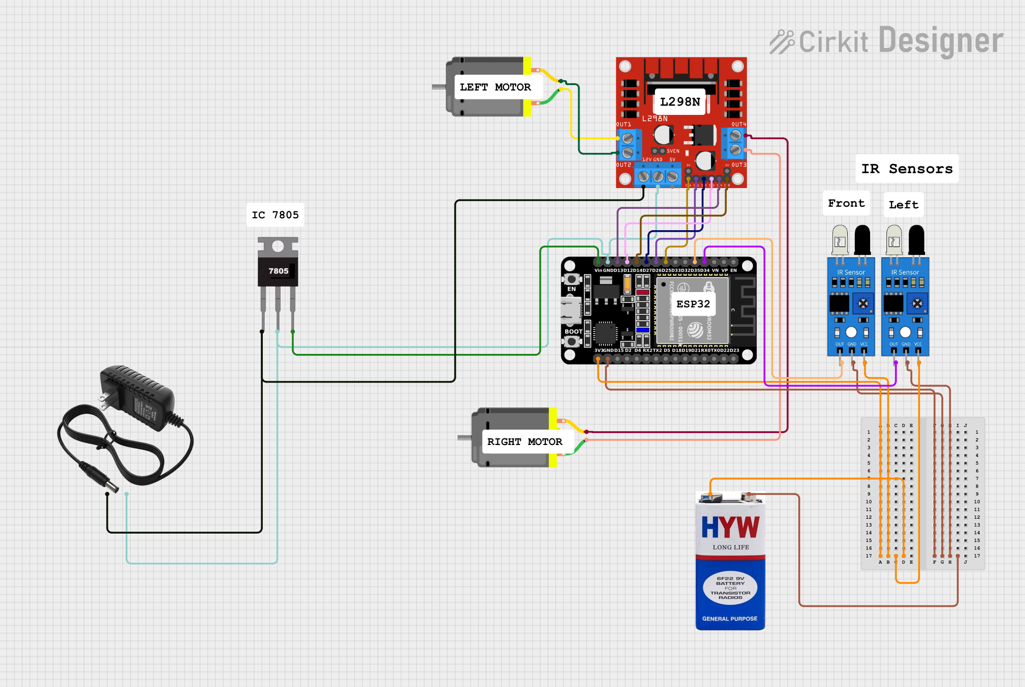
Circuit Documentation
Summary
This circuit is designed to control a robot using an ESP32 microcontroller, an L298N motor driver, and IR sensors for obstacle detection. The robot is powered by a 12V power supply and a 9V battery. The ESP32 reads inputs from the IR sensors and controls the motors via the L298N driver to navigate the robot.
Component List
ESP32 (30 pin)
- Description: A powerful microcontroller with built-in Wi-Fi and Bluetooth capabilities.
- Pins: EN, VP, VN, D34, D35, D32, D33, D25, D26, D27, D14, D12, D13, GND, Vin, D23, D22, TX0, RX0, D21, D19, D18, D5, TX2, RX2, D4, D2, D15, 3V3
L298N DC Motor Driver
- Description: A dual H-bridge motor driver that allows control of two DC motors.
- Pins: OUT1, OUT2, 12V, GND, 5V, OUT3, OUT4, 5V-ENA-JMP-I, 5V-ENA-JMP-O, +5V-J1, +5V-J2, ENA, IN1, IN2, IN3, IN4, ENB
DC Motor
- Description: A simple DC motor.
- Pins: pin 1, pin 2
IR Sensor
- Description: An infrared sensor used for obstacle detection.
- Pins: out, gnd, vcc
7805 Voltage Regulator
- Description: A voltage regulator that outputs a stable 5V.
- Pins: Vin, Gnd, Vout
12V Power Supply
- Description: A power supply providing 12V.
- Pins: +, -
9V Battery
- Description: A battery providing 9V.
- Pins: +, -
Wiring Details
ESP32 (30 pin)
- 3V3: Connected to
vccof both IR sensors and+of the 9V battery. - GND: Connected to
gndof both IR sensors,-of the 9V battery,GNDof the 12V power supply,GNDof the L298N motor driver, andGndof the 7805 voltage regulator. - D34: Connected to
outof the first IR sensor. - D35: Connected to
outof the second IR sensor. - D25: Connected to
ENAof the L298N motor driver. - D26: Connected to
IN1of the L298N motor driver. - D27: Connected to
IN2of the L298N motor driver. - D14: Connected to
ENBof the L298N motor driver. - D12: Connected to
IN3of the L298N motor driver. - D13: Connected to
IN4of the L298N motor driver. - Vin: Connected to
Voutof the 7805 voltage regulator.
L298N DC Motor Driver
- ENA: Connected to
D25of the ESP32. - IN1: Connected to
D26of the ESP32. - IN2: Connected to
D27of the ESP32. - ENB: Connected to
D14of the ESP32. - IN3: Connected to
D12of the ESP32. - IN4: Connected to
D13of the ESP32. - OUT1: Connected to
pin 1of the first DC motor. - OUT2: Connected to
pin 2of the first DC motor. - OUT3: Connected to
pin 1of the second DC motor. - OUT4: Connected to
pin 2of the second DC motor. - 12V: Connected to
+of the 12V power supply. - GND: Connected to
GNDof the 12V power supply andGNDof the ESP32.
DC Motor
- First Motor
- pin 1: Connected to
OUT1of the L298N motor driver. - pin 2: Connected to
OUT2of the L298N motor driver.
- pin 1: Connected to
- Second Motor
- pin 1: Connected to
OUT3of the L298N motor driver. - pin 2: Connected to
OUT4of the L298N motor driver.
- pin 1: Connected to
IR Sensor
- First Sensor
- vcc: Connected to
3V3of the ESP32. - gnd: Connected to
GNDof the ESP32. - out: Connected to
D34of the ESP32.
- vcc: Connected to
- Second Sensor
- vcc: Connected to
3V3of the ESP32. - gnd: Connected to
GNDof the ESP32. - out: Connected to
D35of the ESP32.
- vcc: Connected to
7805 Voltage Regulator
- Vin: Connected to
+of the 12V power supply. - Gnd: Connected to
-of the 12V power supply andGNDof the ESP32. - Vout: Connected to
Vinof the ESP32.
12V Power Supply
- +: Connected to
Vinof the 7805 voltage regulator and12Vof the L298N motor driver. - -: Connected to
Gndof the 7805 voltage regulator andGNDof the ESP32.
9V Battery
- +: Connected to
3V3of the ESP32. - -: Connected to
GNDof the ESP32.
Documented Code
ESP32 Code
#define ENA 25
#define IN1 26
#define IN2 27
#define ENB 14
#define IN3 12
#define IN4 13
#define FRONT_IR 32
#define LEFT_IR 35

#define MOTOR_SPEED 150 // Motor speed (range: 0-255)

// Function to move the robot forward
void moveForward() {
  analogWrite(ENA, MOTOR_SPEED);
  analogWrite(ENB, MOTOR_SPEED);
  digitalWrite(IN1, HIGH);
  digitalWrite(IN2, LOW);
  digitalWrite(IN3, HIGH);
  digitalWrite(IN4, LOW);
}

// Function to turn the robot to the right
void turnRight() {
  analogWrite(ENA, MOTOR_SPEED);
  analogWrite(ENB, MOTOR_SPEED);
  digitalWrite(IN1, HIGH);
  digitalWrite(IN2, LOW);
  digitalWrite(IN3, LOW);
  digitalWrite(IN4, HIGH);
}

// Function to stop the robot
void stopRobot() {
  analogWrite(ENA, 0);
  analogWrite(ENB, 0);
}

void setup() {
  // Set motor driver pins as outputs
  pinMode(ENA, OUTPUT);
  pinMode(IN1, OUTPUT);
  pinMode(IN2, OUTPUT);
  pinMode(ENB, OUTPUT);
  pinMode(IN3, OUTPUT);
  pinMode(IN4, OUTPUT);

  // Set IR sensor pins as inputs
  pinMode(FRONT_IR, INPUT);
  pinMode(LEFT_IR, INPUT);

  // Start serial communication for debugging
  Serial.begin(115200);
}

void loop() {
  // Move the robot forward for 2 seconds
  moveForward();
  delay(2000);

  // Stop the robot for 1 second to read sensor values
  stopRobot();
  delay(1000);

  // Read IR sensor values
  int frontSensor = digitalRead(FRONT_IR);
  int leftSensor = digitalRead(LEFT_IR);

  // Debugging: Print sensor values to the Serial Monitor
  Serial.print("Front IR: ");
  Serial.print(frontSensor);
  Serial.print(" | Left IR: ");
  Serial.println(leftSensor);

  // Decide the next action based on sensor readings
  if (frontSensor == LOW && leftSensor == LOW) {
    // No wall detected; keep moving forward
    moveForward();
  } else {
    // Wall detected; turn right
    turnRight();
    delay(2000); // Allow sufficient time for the turn
  }
}
Additional Code for Second Microcontroller
// Include necessary libraries
#include <Arduino.h>

// Define pin connections
#define IR_LEFT_PIN 34       // IR sensor on the left
#define IR_FRONT_PIN 35      // IR sensor at the front
#define MOTOR_LEFT_ENA 25    // Enable pin for the left motor
#define MOTOR_LEFT_IN1 26    // IN1 pin for the left motor
#define MOTOR_LEFT_IN2 27    // IN2 pin for the left motor
#define MOTOR_RIGHT_ENB