Cirkit Designer
Your all-in-one circuit design IDE
Home /
Project Documentation
LM317 Voltage Regulator Circuit for Adjustable Power Supply with Transformer and Diodes

Circuit Documentation
Summary
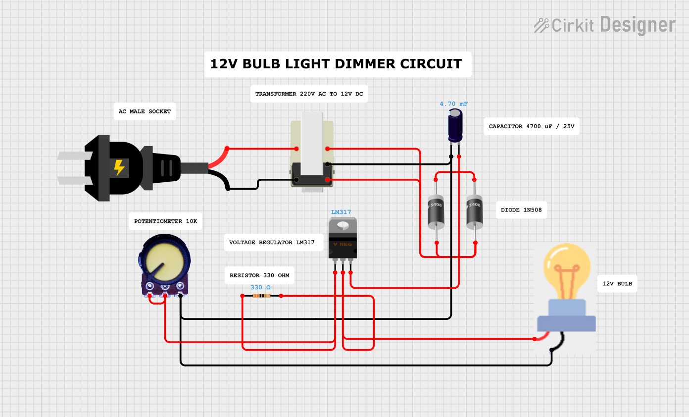
This document provides a detailed overview of a circuit that includes an AC source, a transformer, a voltage regulator, diodes, a resistor, a capacitor, a potentiometer, and a bulb. The circuit is designed to convert AC voltage to a regulated DC voltage, which is then used to power a bulb. The potentiometer is used to adjust the output voltage of the voltage regulator.
Component List
AC Source
- Description: Provides AC voltage to the circuit.
- Pins: +, -
Transformer
- Description: Steps down the AC voltage to a lower level.
- Pins: 1, 2, 3, 4, 5
LM317 Voltage Regulator
- Description: Regulates the output voltage.
- Pins: Adj, V_out, V_in
5408 Diode
- Description: Used for rectification.
- Pins: Anode, Cathode
Resistor
- Description: Limits current in the circuit.
- Properties:
- Resistance: 330 Ohms
- Pins: pin1, pin2
Electrolytic Capacitor
- Description: Filters the rectified voltage.
- Properties:
- Capacitance: 0.0047 Farads
- Pins: +, -
Potentiometer
- Description: Adjusts the output voltage of the voltage regulator.
- Pins: GND, Output, VCC
Bulb
- Description: Indicates the presence of output voltage.
- Pins: GND, Power
Wiring Details
AC Source
- Pin + is connected to Transformer Pin 1.
- Pin - is connected to Transformer Pin 2.
Transformer
- Pin 1 is connected to AC Source Pin +.
- Pin 2 is connected to AC Source Pin -.
- Pin 3 is connected to 5408 Diode Anode.
- Pin 4 is connected to Electrolytic Capacitor Pin - and Potentiometer Pin VCC and Bulb Pin GND.
- Pin 5 is connected to 5408 Diode Anode.
LM317 Voltage Regulator
- Pin Adj is connected to Potentiometer Pin Output and Potentiometer Pin GND and Resistor Pin 1.
- Pin V_out is connected to Bulb Pin Power and Resistor Pin 2.
- Pin V_in is connected to Electrolytic Capacitor Pin +.
5408 Diode
- Anode is connected to Transformer Pin 3 and Transformer Pin 5.
- Cathode is connected to 5408 Diode Cathode.
Resistor
- Pin 1 is connected to LM317 Voltage Regulator Pin Adj and Potentiometer Pin Output and Potentiometer Pin GND.
- Pin 2 is connected to LM317 Voltage Regulator Pin V_out and Bulb Pin Power.
Electrolytic Capacitor
- Pin + is connected to LM317 Voltage Regulator Pin V_in.
- Pin - is connected to Transformer Pin 4 and Potentiometer Pin VCC and Bulb Pin GND.
Potentiometer
- Pin GND is connected to Potentiometer Pin Output and LM317 Voltage Regulator Pin Adj and Resistor Pin 1.
- Pin Output is connected to Potentiometer Pin GND and LM317 Voltage Regulator Pin Adj and Resistor Pin 1.
- Pin VCC is connected to Transformer Pin 4 and Electrolytic Capacitor Pin - and Bulb Pin GND.
Bulb
- Pin GND is connected to Transformer Pin 4 and Electrolytic Capacitor Pin - and Potentiometer Pin VCC.
- Pin Power is connected to LM317 Voltage Regulator Pin V_out and Resistor Pin 2.
Code
There is no microcontroller code associated with this circuit.
This document provides a comprehensive overview of the circuit, including a summary, component list, wiring details, and code documentation.