
Circuit Documentation
Summary
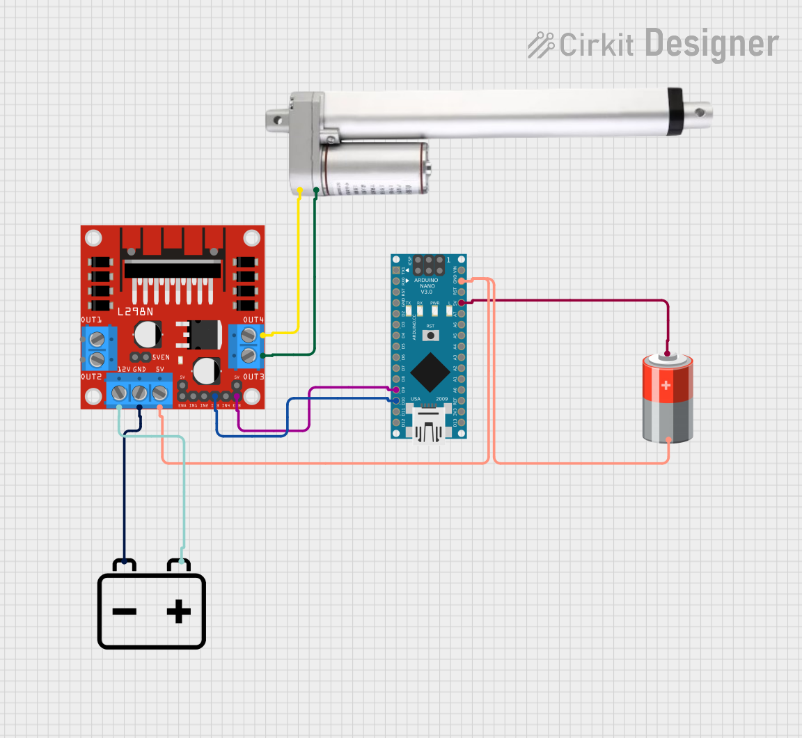
This circuit is designed to control an actuator motor using an Arduino Nano microcontroller and an L298N DC motor driver. The Arduino Nano interfaces with the L298N driver to regulate the motor's operation. Power is supplied to the circuit through a 5V battery connected to the Arduino Nano and a 12V battery connected to the L298N motor driver. The motor driver then powers the actuator motor.
Component List
Arduino Nano
- Microcontroller board based on the ATmega328P
- It has a variety of digital and analog I/O pins
- Can be powered via the USB connection or with an external power supply
L298N DC Motor Driver
- A module that can control up to two DC motors
- Has an onboard 5V regulator which can be connected to the 5V logic power supply
- Supports a supply voltage of up to 35V for driving motors
Actuator Motor
- A motor that converts electrical energy into mechanical motion
- Typically used for applications requiring movement or force application
5V Battery
- Provides the power supply for the logic level components
- Typically a rechargeable battery pack or a set of batteries in series
12V Battery
- Supplies power to the motor driver for driving the actuator motor
- Higher voltage to provide the necessary current and torque
Wiring Details
Arduino Nano
- D9 connected to L298N DC motor driver ENB
- D10 connected to L298N DC motor driver IN3
- GND connected to 5V Battery negative terminal and L298N DC motor driver GND
- 5V connected to 5V Battery positive terminal
L298N DC Motor Driver
- ENB connected to Arduino Nano D9
- IN3 connected to Arduino Nano D10
- 5V connected to 5V Battery negative terminal
- GND connected to 12V Battery negative terminal
- 12V connected to 12V Battery positive terminal
- OUT3 connected to Actuator Motor Ground
- OUT4 connected to Actuator Motor 12 V
Actuator Motor
- Ground connected to L298N DC motor driver OUT3
- 12 V connected to L298N DC motor driver OUT4
5V Battery
- + connected to Arduino Nano 5V
- - connected to Arduino Nano GND and L298N DC motor driver 5V
12V Battery
- + connected to L298N DC motor driver 12V
- - connected to L298N DC motor driver GND
Documented Code
The provided code files for the Arduino Nano are empty. To fully document the code, it would be necessary to have the actual source code that is intended to run on the Arduino Nano. The code would typically include setup and loop functions, with the setup function initializing the pins and the loop function containing the main logic for controlling the motor via the L298N driver.
// Example Arduino Sketch (sketch.ino)
void setup() {
  // Initialize the motor control pins
  pinMode(9, OUTPUT); // ENB
  pinMode(10, OUTPUT); // IN3
}

void loop() {
  // Example logic to control the motor
  digitalWrite(9, HIGH); // Enable motor driver channel B
  digitalWrite(10, HIGH); // Set IN3 to high to drive the motor in a particular direction
  delay(1000); // Run the motor for 1 second
  digitalWrite(10, LOW); // Set IN3 to low to stop the motor
  delay(1000); // Wait for 1 second
}
Please note that the above code is a simple example and does not represent the actual functionality of the provided circuit. The actual code would need to be written based on the specific requirements of the application.