
ESP32-CAM Smart Security System with PIR Sensor and BMP280, Battery-Powered and Wi-Fi Controlled
View and Edit Project In Cirkit Designer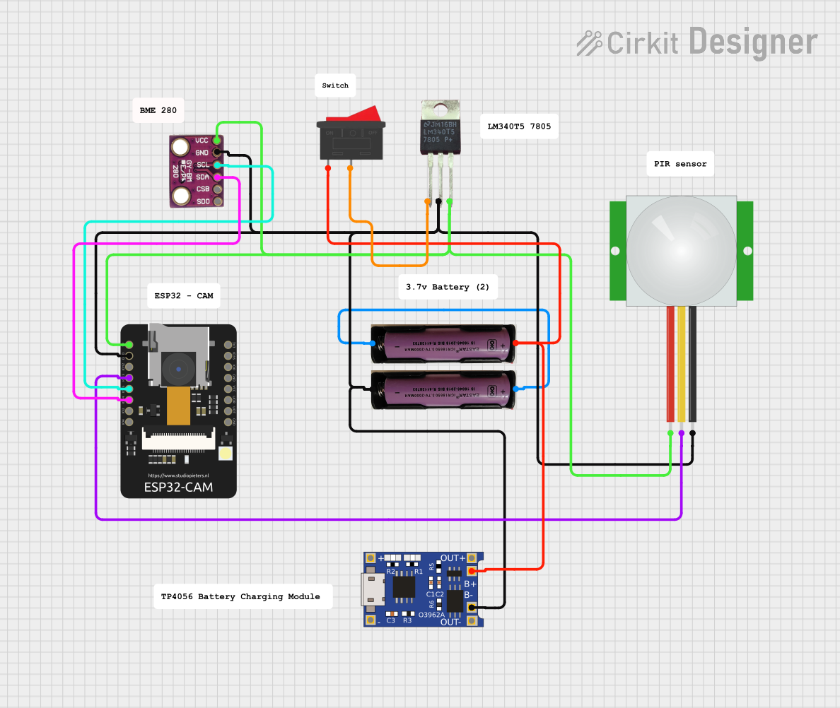
Circuit Documentation
Summary
This circuit is designed to use an ESP32-CAM module to capture images and send them via Telegram when motion is detected by a PIR sensor. The circuit also includes a BMP280 sensor for temperature and humidity readings. Power is managed using a 3.7V battery, a TP4056 charging module, and an LM340T5 7805 voltage regulator. A rocker switch is used to control the power supply.
Component List
ESP32-CAM
- Description: A microcontroller with a built-in camera module.
- Pins: 5V, GND, IO12, IO13, IO15, IO14, IO2, IO4, VOT, VOR, VCC, IO0, IO16, 3V3
PIR Sensor
- Description: A passive infrared sensor used to detect motion.
- Pins: VDD, SIG, GND
3.7V Battery
- Description: A rechargeable lithium-ion battery.
- Pins: +, -
LM340T5 7805
- Description: A voltage regulator that converts 7-25V input to a stable 5V output.
- Pins: Vout, Vin, GND
TP4056
- Description: A lithium battery charger module.
- Pins: OUT-, B-, B+, OUT+, IN-, IN+
BMP280
- Description: A sensor for measuring temperature and humidity.
- Pins: SDO, CSB, SDA, SCL, GND, VCC
Rocker Switch
- Description: A switch to control the power supply.
- Pins: 1, 2
Wiring Details
ESP32-CAM
- 5V: Connected to VCC of BMP280, Vout of LM340T5 7805, and VDD of PIR sensor.
- GND: Connected to GND of BMP280, GND of LM340T5 7805, B- of TP4056, and GND of PIR sensor.
- IO13: Connected to SIG of PIR sensor.
- IO15: Connected to SCL of BMP280.
- IO14: Connected to SDA of BMP280.
PIR Sensor
- VDD: Connected to 5V of ESP32-CAM.
- SIG: Connected to IO13 of ESP32-CAM.
- GND: Connected to GND of ESP32-CAM.
3.7V Battery
- +: Connected to B+ of TP4056 and pin 1 of Rocker Switch.
- -: Connected to GND of ESP32-CAM and B- of TP4056.
LM340T5 7805
- Vout: Connected to 5V of ESP32-CAM.
- Vin: Connected to pin 2 of Rocker Switch.
- GND: Connected to GND of ESP32-CAM.
TP4056
- B+: Connected to + of 3.7V Battery and pin 1 of Rocker Switch.
- B-: Connected to GND of ESP32-CAM.
- OUT+: Not used.
- OUT-: Not used.
- IN+: Not used.
- IN-: Not used.
BMP280
- VCC: Connected to 5V of ESP32-CAM.
- GND: Connected to GND of ESP32-CAM.
- SDA: Connected to IO14 of ESP32-CAM.
- SCL: Connected to IO15 of ESP32-CAM.
Rocker Switch
- Pin 1: Connected to B+ of TP4056 and + of 3.7V Battery.
- Pin 2: Connected to Vin of LM340T5 7805.
Code Documentation
ESP32-CAM Code
#include <WiFi.h>
#include <WiFiClientSecure.h>
#include "soc/soc.h"
#include "soc/rtc_cntl_reg.h"
#include "esp_camera.h"
#include <UniversalTelegramBot.h>
#include <ArduinoJson.h>
#include <Wire.h>
#include "SparkFunBME280.h"

// Replace with your network credentials
const char* ssid = "Yellow";
const char* password = "420420420";

// Use @myidbot to find out the chat ID of an individual or a group
// Also note that you need to click "start" on a bot before it can
// message you
String chatId = "6956280460";

// Initialize Telegram BOT
String BOTtoken = "6982411042:AAFFZX-Ko8iEify37XkN1MlpYPgw7wDUsuc";

bool sendPhoto = false;

WiFiClientSecure clientTCP;

UniversalTelegramBot bot(BOTtoken, clientTCP);

//CAMERA_MODEL_AI_THINKER
#define PWDN_GPIO_NUM     32
#define RESET_GPIO_NUM    -1
#define XCLK_GPIO_NUM      0
#define SIOD_GPIO_NUM     26
#define SIOC_GPIO_NUM     27

#define Y9_GPIO_NUM       35
#define Y8_GPIO_NUM       34
#define Y7_GPIO_NUM       39
#define Y6_GPIO_NUM       36
#define Y5_GPIO_NUM       21
#define Y4_GPIO_NUM       19
#define Y3_GPIO_NUM       18
#define Y2_GPIO_NUM        5
#define VSYNC_GPIO_NUM    25
#define HREF_GPIO_NUM     23
#define PCLK_GPIO_NUM     22

#define FLASH_LED_PIN 4
bool flashState = LOW;

// Motion Sensor
bool motionDetected = false;

// Define I2C Pins for BME280
#define I2C_SDA 14
#define I2C_SCL 15

BME280 bme;

int botRequestDelay = 1000;   // mean time between scan messages
long lastTimeBotRan;     // last time messages' scan has been done

void handleNewMessages(int numNewMessages);
String sendPhotoTelegram();

// Get BME280 sensor readings and return them as a String variable
String getReadings(){
  float temperature, humidity;
  temperature = bme.readTempC();
  //temperature = bme.readTempF();
  humidity = bme.readFloatHumidity();
  String message = "Temperature: " + String(temperature) + " ºC \\n";
  message += "Humidity: " + String (humidity) + " % \\n";
  return message;
}

// Indicates when motion is detected
static void IRAM_ATTR detectsMovement(void * arg){
  //Serial.println("MOTION DETECTED!!!");
  motionDetected = true;
}

void setup(){
  WRITE_PERI_REG(RTC_CNTL_BROWN_OUT_REG, 0);
  Serial.begin(115200);

  pinMode(FLASH_LED_PIN, OUTPUT);
  digitalWrite(FLASH_LED_PIN, flashState);

  // Init BME280 sensor
  Wire.begin(I2C_SDA, I2C_SCL);
  bme.settings.commInterface = I2C_MODE;
  bme.settings.I2CAddress = 0x76;
  bme.settings.runMode = 3;
  bme.settings.tStandby = 0;
  bme.settings.filter = 0;
  bme.settings.tempOverSample = 1;
  bme.settings.pressOverSample = 1;
  bme.settings.humidOverSample = 1;
  bme.begin();

  WiFi.mode(WIFI_STA);
  Serial.println();
  Serial.print("Connecting to ");
  Serial.println(ssid);
  WiFi.begin(ssid, password);
  clientTCP.setCACert(TELEGRAM_CERTIFICATE_ROOT); // Add root certificate for api.telegram.org
  while (WiFi.status() != WL_CONNECTED) {
    Serial.print(".");
    delay(500);
  }
  Serial.println();
  Serial.print("ESP32-CAM IP Address: ");
  Serial.println(WiFi.localIP());

  camera_config_t config;
  config.ledc_channel = LEDC_CHANNEL_0;
  config.ledc_timer = LEDC_TIMER_0;
  config.pin_d0 = Y2_GPIO_NUM;
  config.pin_d1 = Y3_GPIO_NUM;
  config.pin_d2 = Y4_GPIO_NUM;
  config.pin_d3 = Y5_GPIO_NUM;
  config.pin_d4 = Y6_GPIO_NUM;
  config.pin_d5 = Y7_GPIO_NUM;
  config.pin_d6 = Y8_GPIO_NUM;
  config.pin_d7 = Y9_GPIO_NUM;
  config.pin_xclk = XCLK_GPIO_NUM;
  config.pin_pclk = PCLK_GPIO_NUM;
  config.pin_vsync = VSYNC_GPIO_NUM;
  config.pin_href = HREF_GPIO_NUM;
  config.pin_sscb_sda = SIOD_GPIO_NUM;
  config.pin_sscb_scl = SIOC_GPIO_NUM;
  config.pin_pwdn = PWDN_GPIO_NUM;
  config.pin_reset = RESET_GPIO_NUM;
  config.xclk_freq_hz = 20000000;
  config.pixel_format = PIXFORMAT_JPEG;

  //init with high specs to pre-allocate larger buffers
  if(psramFound()){
    config.frame_size = FRAMESIZE_UXGA;
    config.jpeg_quality