
ESP32-Powered Ultrasonic Distance Measurement with I2C LCD Display
View and Edit Project In Cirkit Designer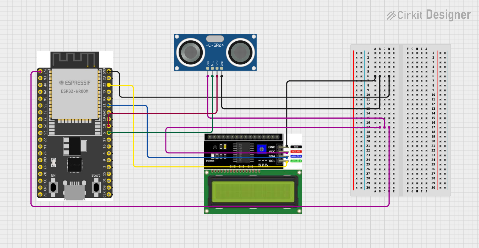
Circuit Documentation
Summary of the Circuit
The circuit in question appears to be designed for distance measurement and display purposes. It consists of an HC-SR04 Ultrasonic Sensor for measuring distances, an LCD I2C Display for showing the measured values, and an ESP 32 Wroom Dev Kit microcontroller for processing the sensor data and controlling the display.
Component List
HC-SR04 Ultrasonic Sensor
- Pins: VCC, TRIG, ECHO, GND
- Description: This sensor is used for measuring distances by emitting ultrasonic waves and measuring the time taken for the echo to return.
LCD I2C Display
- Pins: GND, VCC, SDA, SCL
- Description: An LCD display with an I2C interface used to show information, such as the distance measured by the ultrasonic sensor.
ESP 32 Wroom Dev Kit
- Pins: 3V3, EN, VP, VN, GPIO 34, GPIO 35, GPIO 32, GPIO 33, GPIO 25, GPIO 26, GPIO 27, GPIO 14, GND, GPIO 13, SD2, SD3, CMD, V5, GPIO 23, GPIO 22, TXD, RXD, GPIO 21, GPIO 19, GPIO 18, GPIO 5, GPIO 17, GPIO 16, GPIO 4, GPIO 0, GPIO 2, GPIO 15, SD1, SD0, CLK
- Description: A microcontroller development board based on the ESP32 chip, which is used for controlling the sensor and the display, as well as possibly providing connectivity options.
Wiring Details
HC-SR04 Ultrasonic Sensor
- VCC: Connected to the 3V3 output of the ESP 32 Wroom Dev Kit.
- TRIG: Connected to GPIO 5 of the ESP 32 Wroom Dev Kit.
- ECHO: Connected to GPIO 18 of the ESP 32 Wroom Dev Kit.
- GND: Connected to the GND pin of the ESP 32 Wroom Dev Kit.
LCD I2C Display
- GND: Connected to the GND pin of the ESP 32 Wroom Dev Kit.
- VCC: Connected to the 3V3 output of the ESP 32 Wroom Dev Kit.
- SDA: Connected to GPIO 21 of the ESP 32 Wroom Dev Kit.
- SCL: Connected to GPIO 22 of the ESP 32 Wroom Dev Kit.
ESP 32 Wroom Dev Kit
- 3V3: Provides power to the HC-SR04 Ultrasonic Sensor and the LCD I2C Display.
- GND: Common ground for the circuit.
- GPIO 5: Outputs trigger signal to the HC-SR04 Ultrasonic Sensor.
- GPIO 18: Receives echo signal from the HC-SR04 Ultrasonic Sensor.
- GPIO 21: Connected to the SDA pin of the LCD I2C Display.
- GPIO 22: Connected to the SCL pin of the LCD I2C Display.
Documented Code
No code has been provided for the microcontroller. The expected code should initialize the sensor and display, read the distance measurements from the sensor, process the data, and then output the results to the LCD display. The code would typically be written in C or C++ for the ESP32 microcontroller, using the appropriate libraries for handling I2C communication and timing for the ultrasonic sensor.