
Circuit Documentation
Summary of the Circuit
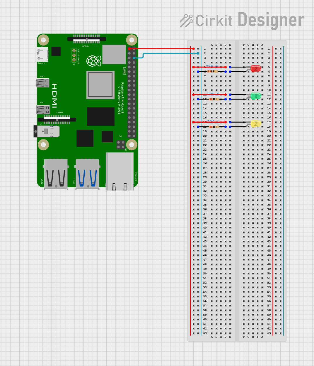
This circuit appears to be a simple LED array controlled by a Raspberry Pi 4B. There are three LEDs of different colors (red, green, and yellow), each with a corresponding current-limiting resistor. The anodes of the LEDs are connected to the 3.3V power supply through the Raspberry Pi, while the cathodes are connected to the ground (GND) through the resistors. This setup ensures that the LEDs are properly powered and protected from excessive current that could potentially damage them.
Component List
LED: Two Pin (red)
- Description: A red light-emitting diode (LED) with two pins: an anode and a cathode.
- Purpose: To emit red light when powered.
LED: Two Pin (green)
- Description: A green light-emitting diode (LED) with two pins: an anode and a cathode.
- Purpose: To emit green light when powered.
LED: Two Pin (yellow)
- Description: A yellow light-emitting diode (LED) with two pins: an anode and a cathode.
- Purpose: To emit yellow light when powered.
Resistor (220 Ohms)
- Description: A resistor with a resistance of 220 Ohms.
- Purpose: To limit the current flowing through the LEDs, protecting them from damage.
Raspberry Pi 4B
- Description: A small single-board computer with multiple GPIO pins.
- Purpose: To control the LEDs and potentially run other applications.
Wiring Details
LED: Two Pin (red)
- Cathode: Connected to the 3.3V power supply through the Raspberry Pi.
- Anode: Connected to the ground (GND) through a 220 Ohm resistor.
LED: Two Pin (green)
- Cathode: Connected to the 3.3V power supply through the Raspberry Pi.
- Anode: Connected to the ground (GND) through a 220 Ohm resistor.
LED: Two Pin (yellow)
- Cathode: Connected to the 3.3V power supply through the Raspberry Pi.
- Anode: Connected to the ground (GND) through a 220 Ohm resistor.
Resistor (220 Ohms)
- Pin1: Connected to the ground (GND) on the Raspberry Pi.
- Pin2: Connected to the anode of the corresponding LED.
Raspberry Pi 4B
- 3V3: Connected to the cathodes of all three LEDs.
- GND: Connected to pin1 of all three resistors.
Documented Code
No code has been provided for the microcontrollers in the circuit. If code is later provided, it should be documented here, including a description of what each part of the code does, how it interacts with the hardware components, and any relevant algorithms or logic used.