Arduino UNO Controlled LED Display with 74HC595 Shift Register
Circuit Documentation
Summary
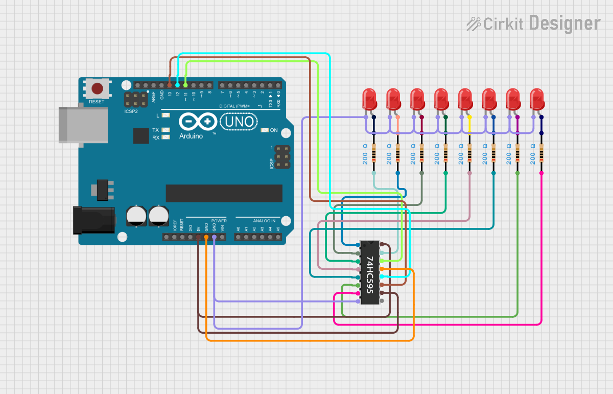
This circuit utilizes an Arduino UNO microcontroller to control a series of red LEDs through a 74HC595 shift register. The shift register allows for the sequential control of multiple LEDs using only a few pins from the Arduino. Each LED is connected through a 200 Ohm resistor to limit the current and prevent damage to the LEDs. The circuit is designed to sequentially turn on each LED connected to the outputs of the shift register.
Component List
1. Arduino UNO
- Description: A microcontroller board based on the ATmega328P.
- Purpose: Acts as the main controller for the circuit, sending signals to the shift register to control the LEDs.
2. 74HC595 Shift Register
- Description: An 8-bit shift register that can be used to control multiple outputs.
- Purpose: Allows the Arduino to control multiple LEDs using only three pins.
3. LED Two Pin (Red)
- Description: A standard red LED with two pins (anode and cathode).
- Purpose: Provides visual indication by lighting up when powered.
4. Resistor
- Description: A passive electrical component that resists the flow of current.
- Purpose: Limits the current flowing through the LEDs to prevent damage. Each resistor has a resistance of 200 Ohms.
Wiring Details
Arduino UNO
5V: Connected to the VCC pin of the 74HC595 shift register.
GND: Connected to the GND pins of the 74HC595 shift register and all LEDs.
D13: Connected to the SRCLK pin of the 74HC595 shift register.
D12: Connected to the RCLK pin of the 74HC595 shift register.
D11: Connected to the SER pin of the 74HC595 shift register.
74HC595 Shift Register
VCC: Connected to the 5V pin of the Arduino UNO.
GND: Connected to the GND pin of the Arduino UNO.
OE: Connected to GND to enable the output.
SRCLR: Connected to the 5V pin of the Arduino UNO.
SER: Connected to D11 of the Arduino UNO.
SRCLK: Connected to D13 of the Arduino UNO.
RCLK: Connected to D12 of the Arduino UNO.
QA to QH: Each output pin (QA to QH) is connected to the anode of a corresponding LED through a 200 Ohm resistor.
LED Two Pin (Red)
Anode: Connected to the output pins (QA to QH) of the 74HC595 shift register through a 200 Ohm resistor.
Cathode: Connected to the GND pin of the Arduino UNO.
Resistor
Pin1: Connected to the output pins (QA to QH) of the 74HC595 shift register.
Pin2: Connected to the anode of the corresponding LED.
Documented Code
/*
 * Arduino Sketch to test the 74HC595 shift register.
 * This code will sequentially turn on each LED connected to the shift register
 * outputs QA to QH. Each LED is connected through a 200 Ohm resistor.
 * The shift register is controlled via the Arduino UNO using pins:
 * - SER (Serial Data Input) on D11
 * - SRCLK (Shift Register Clock) on D13
 * - RCLK (Storage Register Clock) on D12
 */

const int dataPin = 11;   // SER pin on 74HC595
const int clockPin = 13;  // SRCLK pin on 74HC595
const int latchPin = 12;  // RCLK pin on 74HC595

void setup() {
  // Set pins as outputs
  pinMode(dataPin, OUTPUT);
  pinMode(clockPin, OUTPUT);
  pinMode(latchPin, OUTPUT);
}

void loop() {
  // Loop through each LED
  for (int i = 0; i < 8; i++) {
    // Shift out the bit pattern
    shiftOut(dataPin, clockPin, MSBFIRST, 1 << i);
    // Latch the output to display the current LED
    digitalWrite(latchPin, LOW);
    digitalWrite(latchPin, HIGH);
    // Wait for a second
    delay(1000);
  }
}
This documentation provides a comprehensive overview of the circuit, detailing the components used, their connections, and the code that drives the functionality of the circuit.