
Arduino Mega-Controlled Robotic Arm with Servos and Solenoid Actuators
View and Edit Project In Cirkit Designer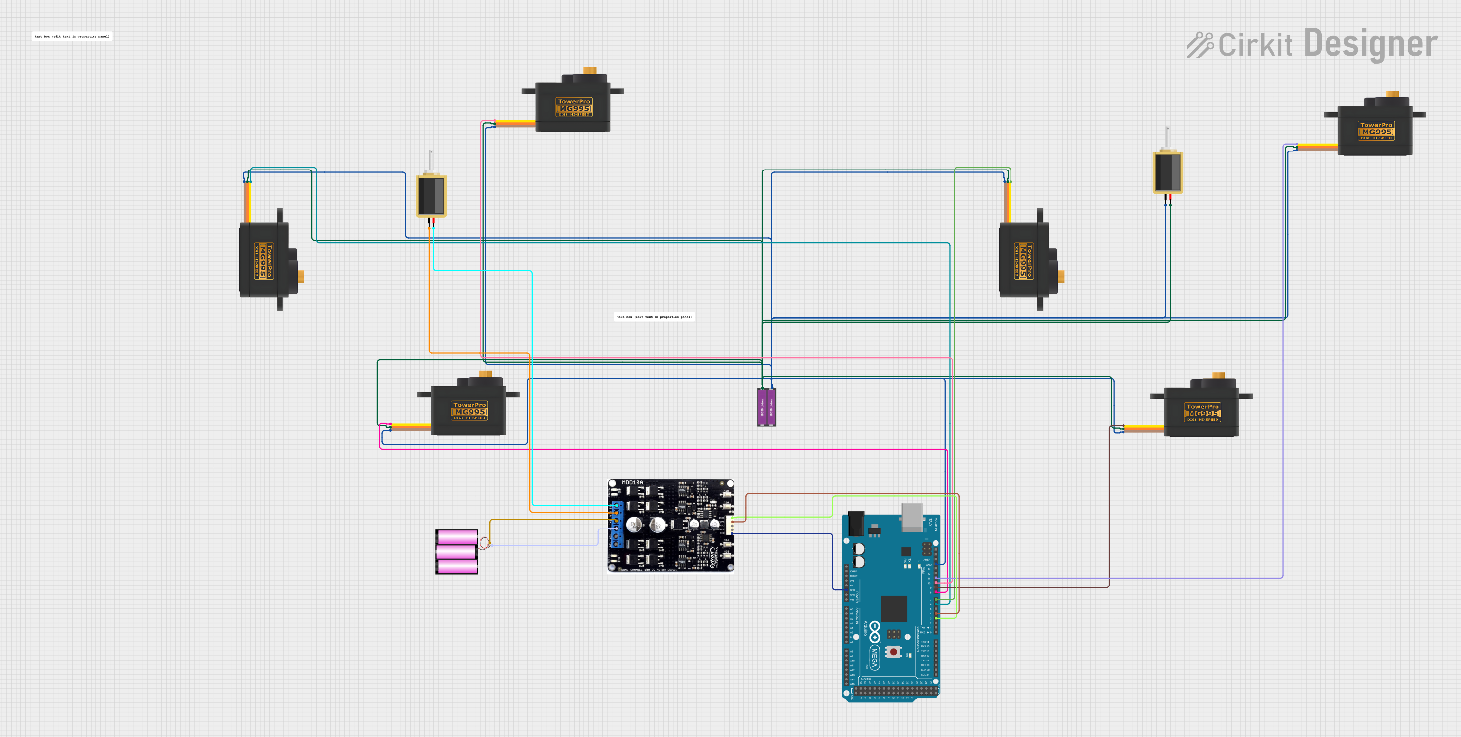
Circuit Documentation
Summary
The circuit in question is designed to control multiple servomotors, a solenoid, and a motor driver module using an Arduino Mega 2560 microcontroller. The servomotors are likely used for precise movement or positioning, while the solenoid is an electromechanical device that can be used for actuation or locking mechanisms. The motor driver module interfaces with the microcontroller to control the speed and direction of a motor. The circuit is powered by a combination of 18650 Li-ion batteries and a 12V battery, which suggests that the system is designed for portable or remote applications where a mains power supply is not available.
Component List
Microcontroller
- Arduino Mega 2560: A microcontroller board based on the ATmega2560, with a large number of IO pins, including PWM, digital, and analog inputs.
Actuators
- Servomotor MG995: A high-torque metal gear servo used for precise control of mechanical components.
- Solenoid: An electromagnetic actuator used for creating linear motion.
Power Sources
- 18650 Li-ion Battery x 2: A rechargeable battery pack providing a power source for the circuit.
- Battery 12V: A 12V battery used to provide power to the motor driver and connected loads.
Motor Driver
- Cytron: A motor driver module capable of controlling the direction and speed of motors.
Miscellaneous
- Comment: A placeholder for additional notes or comments in the circuit design.
Wiring Details
Arduino Mega 2560
- Digital Pin D6 PWM: Connected to Servomotor MG995 (Signal)
- Digital Pin D8 PWM: Connected to Servomotor MG995 (Signal)
- Digital Pin D10 PWM: Connected to Servomotor MG995 (Signal)
- Digital Pin D7 PWM: Connected to Servomotor MG995 (Signal)
- Digital Pin D9 PWM: Connected to Servomotor MG995 (Signal)
- Digital Pin D11 PWM: Connected to Servomotor MG995 (Signal)
- Digital Pin D3 PWM: Connected to Cytron (DIR1)
- Digital Pin D4 PWM: Connected to Cytron (PWM1)
- GND Pins: Connected to the ground pins of all Servomotors, Solenoid, and Cytron
Servomotor MG995
- SIG: Connected to respective PWM pins on the Arduino Mega 2560
- VCC: All connected together and to the positive terminal of the 18650 Li-ion Battery x 2
- GND: All connected together and to the ground terminal of the 18650 Li-ion Battery x 2
Solenoid
- Pin1: Connected to Cytron (M1A) and to the ground terminal of the 18650 Li-ion Battery x 2
- Pin2: Connected to Cytron (M1B) and to the positive terminal of the 18650 Li-ion Battery x 2
Cytron
- M1A, M1B: Connected to the Solenoid
- DIR1: Connected to Arduino Mega 2560 (D3 PWM)
- PWM1: Connected to Arduino Mega 2560 (D4 PWM)
- B+: Connected to the positive terminal of the 12V battery
- B-: Connected to the negative terminal of the 12V battery
- GND: Connected to the ground pin of the Arduino Mega 2560
18650 Li-ion Battery x 2
- +: Connected to the VCC pins of all Servomotors and to the Solenoid (Pin2)
- -: Connected to the GND pins of all Servomotors and to the Solenoid (Pin1)
Battery 12V
- +: Connected to Cytron (B+)
- -: Connected to Cytron (B-)
Documented Code
Arduino Mega 2560 Code
#include "CytronMotorDriver.h"
#include <Servo.h>

#define grabber1 22 // right grabber
#define grabber2 26 // left grabber

Servo servo1; // platform servo 25 Kg (right)
Servo servo2; // left
Servo servo3; // linkage servo 60kg (right)
Servo servo4; // left
Servo servo5; // path servo 15 kg (right)
Servo servo6; // left
int pos1 = 0; // platform servo
int pos2 = 0; // linkage servo
int pos3 = 0; // path servo
CytronMD motor1(PWM_DIR, 3, 4);

void Rock() // function for loading sapling to grabbers and travel them up to hold and convey
{
  digitalWrite(grabber1, 1);
  digitalWrite(grabber2, 1);
  Serial.print("Plants has been grabbed");
  Serial.println();
  delay(500);

  for (pos1 = 0; pos1 <= 90; pos1 += 1) // platform servo controller
  {
    servo1.write(pos1);
    servo2.write(pos1);
    delay(10);
  }
  delay(100);
  Serial.print("platform has moved up");
  Serial.println();
  for (pos2 = 0; pos2 <= 90; pos2 += 1) {
    servo3.write(pos2);
    servo4.write(pos2);
    delay(15);
  }
  delay(400);
  digitalWrite(grabber1, 0);
  digitalWrite(grabber2, 0);
  Serial.print("plants have been released");
  Serial.println();
}

void lock() {
  for (pos1 = 90; pos1 >= 0; pos1 -= 1) {
    servo1.write(pos1);
    servo2.write(pos1);
    delay(10);
  }
  delay(100);
  Serial.print("The platform has shifted to down");
  Serial.println();

  for (pos2 = 90; pos2 >= 0; pos2 -= 1) {
    servo3.write(pos2);
    servo4.write(pos2);
    delay(15);
  }
  delay(500);
  Serial.print("Grabbers has returned to loading position");
  Serial.println();
}

void setup() {
  servo1.attach(6);
  servo2.attach(7);
  servo3.attach(8);
  servo4.attach(9);
  servo5.attach(10);
  servo6.attach(11);
  pinMode(grabber1, OUTPUT);
  pinMode(grabber2, OUTPUT);
  Serial.begin(9600); // initializing serial monitor at 9600 baud rate for knowing the processing going on
  Serial.print("make sure that every servo should be at zero position");
  Serial.println();
}

void loop() {
  Serial.print("let's lock and Rock");
  Serial.println();

  Rock();

  for (pos3 = 0; pos3 <= 90; pos3 += 15) {
    servo5.write(pos3);
    servo6.write(pos3);
    delay(100);
  }
  Serial.print("The path has been changed to another slot");
  Serial.println();
  lock();
  delay(500);
  Rock();
  for (pos3 = 90; pos3 >= 0; pos3 -= 15) {
    servo5.write(pos3);
    servo6.write(pos3);
    delay(100);
  }
  motor1.setSpeed(255);
  delay(100); // delay will be dependent on time required to move tray by 3.9 cm with actuator
  motor1.setSpeed(0);
  lock();
  delay(500);
}
Cytron Code
void setup() {
  // put your setup code here, to run once:
}

void loop() {
  // put your main code here, to run repeatedly:
}
This concludes the documentation for the provided circuit design and embedded code.