
Arduino Nano-Based Wireless Light Intensity Sensor with NRF24L01
View and Edit Project In Cirkit Designer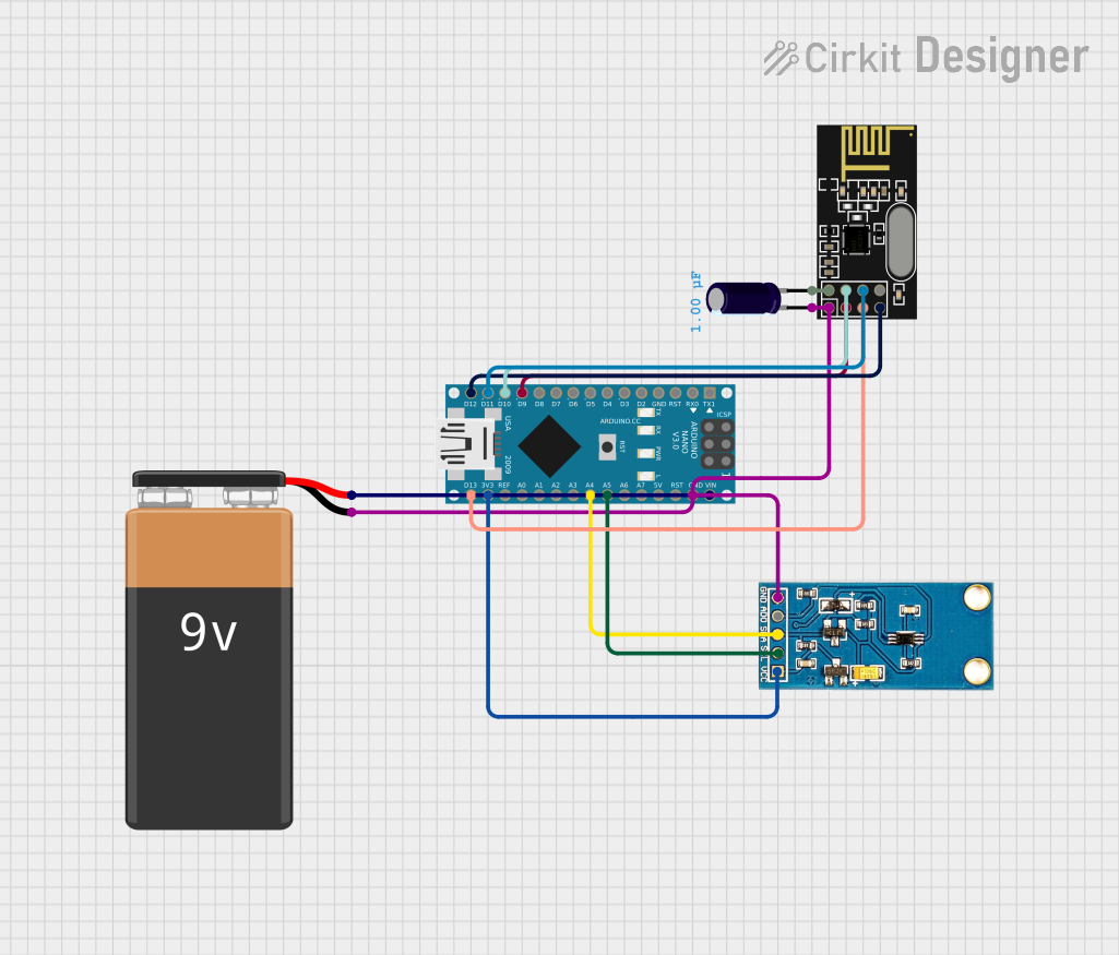
Circuit Documentation
Summary
This circuit involves an Arduino Nano microcontroller interfacing with an NRF24L01 wireless module and a GY-30 BH1750FVI digital light intensity sensor. The circuit is powered by a 9V battery, and an electrolytic capacitor is used for power stabilization.
Component List
Arduino Nano
- Description: A small, complete, and breadboard-friendly board based on the ATmega328P.
- Pins: D1/TX, D0/RX, RESET, GND, D2, D3, D4, D5, D6, D7, D8, D9, D10, D11/MOSI, D12/MISO, VIN, 5V, A7, A6, A5, A4, A3, A2, A1, A0, AREF, 3V3, D13/SCK
NRF24L01
- Description: A wireless transceiver module for low-power, high-speed communication.
- Pins: IRQ (not used), MOSI, CSN, VCC (3V), GND, CE, SCK, MISO
GY-30 BH1750FVI Digital Light Intensity Illumination Sensor
- Description: A digital light sensor module that measures light intensity.
- Pins: Gnd(-) negative, AD0, SDA, SCL, Vcc (3.3v)
Electrolytic Capacitor
- Description: A capacitor used for power stabilization.
- Pins: -, +
- Properties:
- Capacitance: 0.000001 Farads
9V Battery
- Description: A standard 9V battery used to power the circuit.
- Pins: -, +
Wiring Details
Arduino Nano
- D9 connected to NRF24L01 CE
- D10 connected to NRF24L01 CSN
- D11/MOSI connected to NRF24L01 MOSI
- D12/MISO connected to NRF24L01 MISO
- VIN connected to 9V Battery +
- GND connected to 9V Battery -, Electrolytic Capacitor -, NRF24L01 GND, GY-30 BH1750FVI Digital Light Intensity Illumination Sensor Gnd(-) negative
- A5 connected to GY-30 BH1750FVI Digital Light Intensity Illumination Sensor SCL
- A4 connected to GY-30 BH1750FVI Digital Light Intensity Illumination Sensor SDA
- 3V3 connected to GY-30 BH1750FVI Digital Light Intensity Illumination Sensor Vcc (3.3v)
- D13/SCK connected to NRF24L01 SCK
NRF24L01
- CE connected to Arduino Nano D9
- CSN connected to Arduino Nano D10
- MOSI connected to Arduino Nano D11/MOSI
- MISO connected to Arduino Nano D12/MISO
- GND connected to Arduino Nano GND, 9V Battery -, Electrolytic Capacitor -, GY-30 BH1750FVI Digital Light Intensity Illumination Sensor Gnd(-) negative
- SCK connected to Arduino Nano D13/SCK
- VCC (3V) connected to Electrolytic Capacitor +
GY-30 BH1750FVI Digital Light Intensity Illumination Sensor
- Gnd(-) negative connected to Arduino Nano GND, 9V Battery -, Electrolytic Capacitor -, NRF24L01 GND
- SCL connected to Arduino Nano A5
- SDA connected to Arduino Nano A4
- Vcc (3.3v) connected to Arduino Nano 3V3
Electrolytic Capacitor
- - connected to Arduino Nano GND, 9V Battery -, NRF24L01 GND, GY-30 BH1750FVI Digital Light Intensity Illumination Sensor Gnd(-) negative
- + connected to NRF24L01 VCC (3V)
9V Battery
- + connected to Arduino Nano VIN
- - connected to Arduino Nano GND, Electrolytic Capacitor -, NRF24L01 GND, GY-30 BH1750FVI Digital Light Intensity Illumination Sensor Gnd(-) negative
Documented Code
Arduino Nano Code (sketch.ino)
void setup() {
  // put your setup code here, to run once:

}

void loop() {
  // put your main code here, to run repeatedly:

}
Additional Documentation (documentation.txt)