
ESP32-Based Smart Irrigation System with Soil Moisture Sensing and Environmental Monitoring
View and Edit Project In Cirkit Designer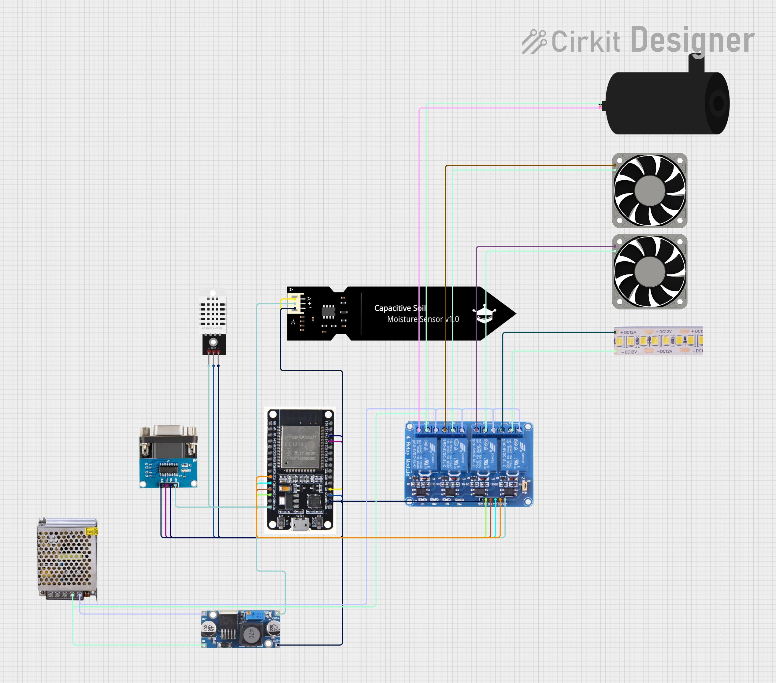
Circuit Documentation
Summary
This circuit is designed to interface an ESP32 microcontroller with various sensors and actuators, including a DHT22 temperature and humidity sensor, a DFRobot Capacitive Soil Moisture Sensor, and a relay module to control power to devices such as a water pump, LED strip, and fans. The circuit includes a step-down buck converter to regulate voltage from a 12V 5A power supply, and an RS232 to TTL converter for serial communication. The ESP32 controls the relay module to switch devices on and off based on sensor readings and programmed logic.
Component List
ESP32
- Microcontroller with WiFi and Bluetooth capabilities.
- It has multiple GPIO pins for interfacing with sensors and actuators.
RS232 to TTL Converter
- Converts RS232 signals to TTL logic levels for use with microcontrollers.
DFRobot Capacitive Soil Moisture Sensor (V1.0)
- Measures the moisture level in the soil using capacitive sensing.
DHT22
- A sensor that measures ambient temperature and humidity.
Step-Down Buck Converter
- Converts higher DC voltage to a lower DC voltage with high efficiency.
POWER SUPPLY 12V 5AMP
- Provides a 12V DC output with a maximum current of 5A.
12V White LED Strip
- A strip of LEDs that operates at 12V for lighting purposes.
40mm Fan 12V
- A 12V fan used for cooling, two instances are present in the circuit.
Relay 4 Channel 5v
- A 4-channel relay module that allows the ESP32 to control high power devices.
Water Pump
- An electric pump for moving water, controlled by the relay module.
Wiring Details
ESP32
D27,D14,D12,D13are connected to the relay module to control the relays.VINis connected to the output of the step-down buck converter to receive power.GNDis connected to the common ground in the circuit.D15is connected to theOutpin of the DHT22 sensor.D2is connected to theApin of the soil moisture sensor.RX0andTX0are connected to theTXDandRXDpins of the RS232 to TTL converter for serial communication.
RS232 to TTL Converter
VCCandGNDare connected to the power supply and common ground, respectively.RXDandTXDare connected toTX0andRX0on the ESP32 for serial communication.
DFRobot Capacitive Soil Moisture Sensor (V1.0)
VCCis connected to the power supply.GNDis connected to the common ground.Ais connected toD2on the ESP32 for analog signal reading.
DHT22
+and-are connected to the power supply and common ground, respectively.Outis connected toD15on the ESP32 for digital signal reading.
Step-Down Buck Converter
IN +andIN - GNDare connected to the 12V power supply output and ground, respectively.OUT +andOUT - GNDprovide regulated voltage to the ESP32 and other 5V components.
POWER SUPPLY 12V 5AMP
- Provides power to the circuit, with the
12V-24V Output (DC)connected to the input of the step-down buck converter and the relay module. GND (DC)is part of the common ground network.
12V White LED Strip
+12VandGNDare connected to the normally closed (NC) contacts of the relay module and common ground, respectively.
40mm Fan 12V
- Both fans have
+12Vconnected to the normally closed (NC) contacts of the relay module. -12Vis connected to the common ground.
Relay 4 Channel 5v
IN1,IN2,IN3,IN4are controlled by the ESP32.VCCis connected to the power supply.GNDis connected to the common ground.COM1,COM2,COM3,COM4are connected to the common ground.NO1,NO2,NO3,NO4are connected to the power supply.NC1,NC2,NC3,NC4are connected to the devices being controlled (water pump, LED strip, fans).
Water Pump
positiveandnegativeare connected to the normally closed (NC) contacts of the relay module and common ground, respectively.
Documented Code
sketch.ino
void setup() {
  // put your setup code here, to run once:

}

void loop() {
  // put your main code here, to run repeatedly:

}
documentation.txt
The code for the ESP32 is currently a template with empty setup() and loop() functions. The setup() function should be used to initialize the GPIO pins, sensors, and communication protocols. The loop() function will contain the main logic for reading sensor data, making decisions, and controlling the relay module to power the connected devices.