
Magnetic Field-Activated Solenoid Array with Arduino Control
View and Edit Project In Cirkit Designer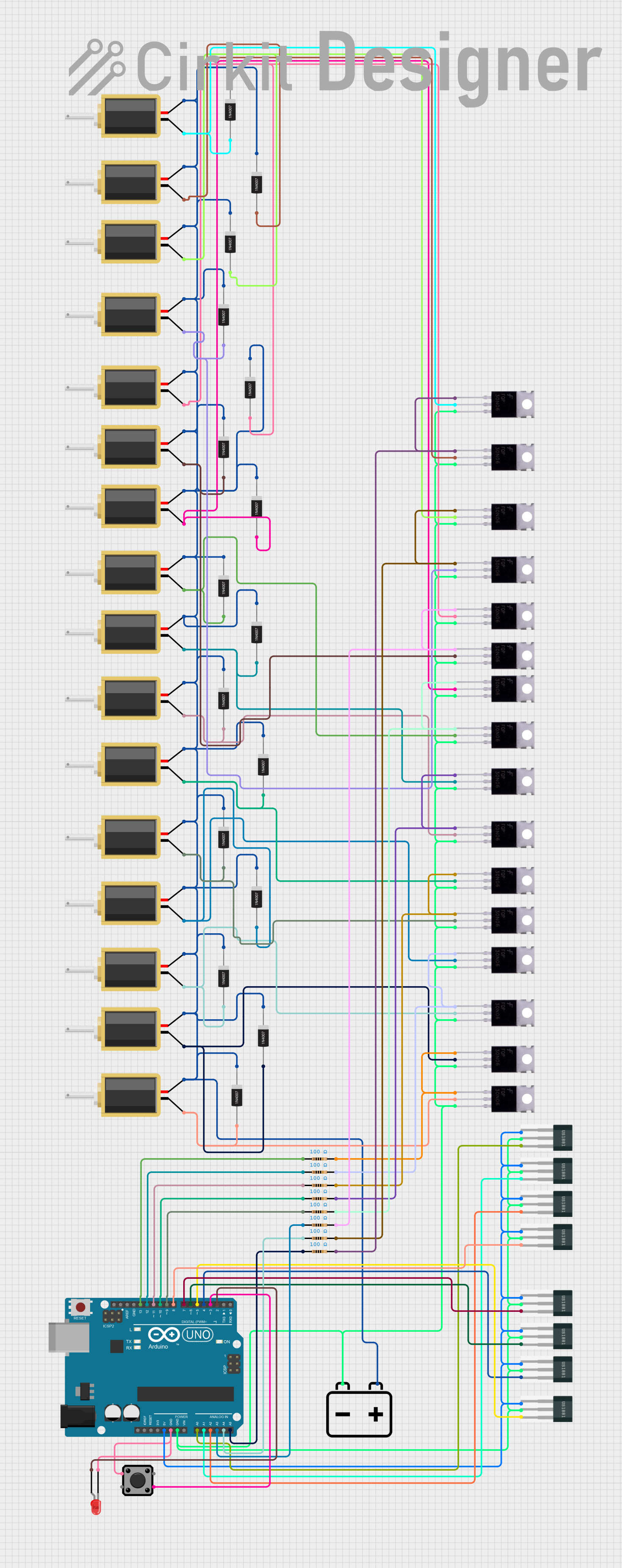
Circuit Documentation
Summary
This circuit appears to be designed to monitor magnetic fields using multiple Hall sensors and control a series of solenoids accordingly. The Arduino UNO microcontroller is used to process the signals from the Hall sensors and drive the solenoids through MOSFETs. The circuit includes protective diodes for the solenoids, resistors for current limiting, and an LED for indication purposes. A 12V battery provides the power source for the solenoids, while the Arduino is powered by its 5V pin.
Component List
Microcontroller
- Arduino UNO: A microcontroller board based on the ATmega328P, equipped with a variety of digital and analog I/O pins.
Sensors
- Hall Sensor: A transducer that varies its output voltage in response to a magnetic field.
Actuators
- Solenoid: An electromagnetic actuator used for creating a controlled magnetic field or exerting a mechanical force.
Semiconductors
- Mosfet: A type of field-effect transistor used for switching and amplifying electronic signals.
- 1N4007 Rectifier Diode: A diode commonly used for rectification and protection against reverse polarity.
- LED: Two Pin (red): A simple red light-emitting diode for indication purposes.
Passive Components
- Resistor: A passive two-terminal electrical component that implements electrical resistance as a circuit element.
Power Supply
- 12v Battery: A power source providing 12 volts to drive the solenoids.
User Interface
- Tactile Switch Buttons - 12mm Square: A simple push-button switch for user input.
Wiring Details
Arduino UNO
- Digital and analog pins connected to Hall sensors and resistors.
- Power pins (5V and GND) connected to Hall sensors and the LED.
- Control pins (D2-D13) connected to MOSFET gates and tactile switch.
Hall Sensors
- "+" pin connected to Arduino GND.
- "-" pin connected to Arduino 5V.
- "S" pin connected to individual analog pins on the Arduino (A0, A1, A2, etc.).
Solenoids
- "pin1" connected to the drain of individual MOSFETs.
- "pin2" connected to the cathode of individual 1N4007 diodes and then to the positive terminal of the 12V battery.
MOSFETs
- "Gate" connected to individual digital pins on the Arduino through resistors.
- "Drain" connected to "pin1" of individual solenoids.
- "Source" connected to Arduino GND.
Resistors
- One end connected to the gate of individual MOSFETs.
- The other end connected to digital pins on the Arduino (D13, D12, D11, etc.).
1N4007 Rectifier Diodes
- "Anode" connected to "pin1" of individual solenoids.
- "Cathode" connected to "pin2" of solenoids and then to the positive terminal of the 12V battery.
LED
- "anode" connected to Arduino digital pin D2.
- "cathode" connected to Arduino GND through the tactile switch.
Tactile Switch
- One side connected to Arduino digital pin D3.
- The other side connected to the cathode of the LED and Arduino GND.
Documented Code
Arduino UNO Code (sketch.ino)
void setup() {
  // put your setup code here, to run once:

}

void loop() {
  // put your main code here, to run repeatedly:

}
Note: The provided code is a template and does not contain any functional code. It needs to be populated with the logic to read the Hall sensors, process the input, and control the solenoids accordingly.