ESP32-Controlled Servo Motor
Circuit Documentation
Summary of the Circuit
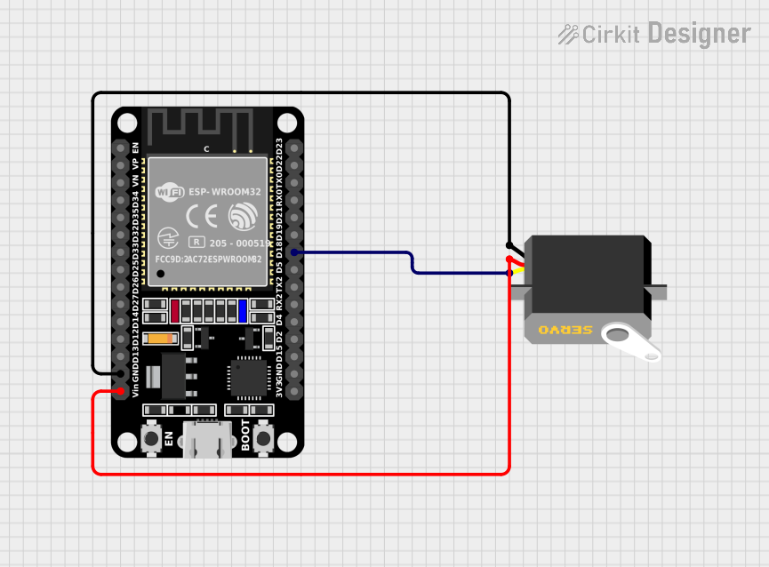
This circuit consists of an ESP32 microcontroller and a servo motor. The ESP32 is a versatile microcontroller with a wide range of I/O capabilities, while the servo motor is an actuator that can be precisely controlled to move to different positions. The ESP32 is used to control the servo by sending pulse-width modulation (PWM) signals to the servo's control line.
Component List
ESP32 (30 pin)
- Description: A 30-pin ESP32 microcontroller module.
- Purpose: Acts as the central processing unit of the circuit, generating control signals for the servo motor and handling any other computational tasks required by the circuit.
- Pins: EN, VP, VN, D34, D35, D32, D33, D25, D26, D27, D14, D12, D13, GND, Vin, D23, D22, TX0, RX0, D21, D19, D18, D5, TX2, RX2, D4, D2, D15, 3V3.
Servo
- Description: A standard servo motor with three connection pins.
- Purpose: Receives control signals from the ESP32 and adjusts its position accordingly.
- Pins: gnd, vcc, pulse.
Wiring Details
ESP32 (30 pin)
- GND: Connected to the ground (gnd) pin of the Servo.
- Vin: Connected to the voltage supply (vcc) pin of the Servo.
- D18: Connected to the control (pulse) pin of the Servo.
Servo
- gnd: Connected to the ground (GND) pin of the ESP32.
- vcc: Connected to the voltage input (Vin) pin of the ESP32.
- pulse: Connected to the digital I/O pin (D18) of the ESP32 for control signals.
Documented Code
There is no code provided for the microcontroller in this circuit. The ESP32 would typically be programmed to generate PWM signals on the D18 pin to control the position of the servo motor. The code would initialize the microcontroller's PWM functionality, calculate the correct pulse widths for the desired servo positions, and output the pulses at regular intervals.
Since no specific code is provided, below is an example of how the ESP32 could be programmed to control the servo motor:
#include <Arduino.h>

const int servoPin = 18; // ESP32 pin connected to the servo pulse line

void setup() {
  // Configure the servo pin as an output
  pinMode(servoPin, OUTPUT);
  // Initialize the servo control signal
  digitalWrite(servoPin, LOW);
}

void loop() {
  // Example of generating a PWM signal to move the servo
  // This would typically be replaced with actual control logic
  digitalWrite(servoPin, HIGH);
  delayMicroseconds(1500); // 1.5 ms pulse width for neutral position
  digitalWrite(servoPin, LOW);
  delay(20); // Wait for 20 ms period
}
This example code is a simple placeholder and does not represent the actual functionality that may be required in a real-world application. It is intended to demonstrate the basic setup and signal generation for controlling a servo with an ESP32.