Arduino UNO and ESP32 CAM Controlled Fire Detection and Alert System with GSM Notification
Circuit Documentation
Summary
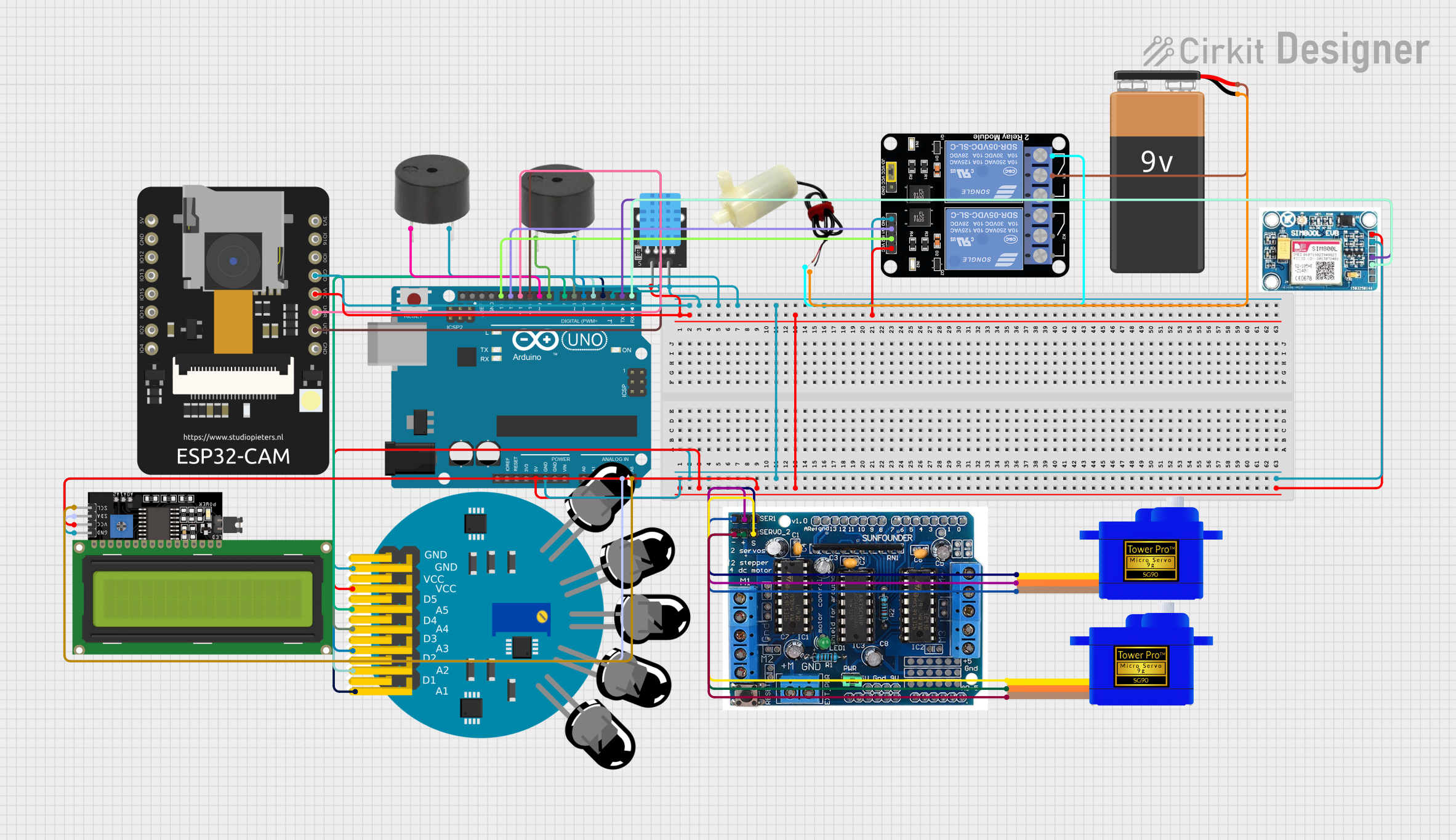
This circuit integrates various components controlled by an Arduino UNO microcontroller to perform a range of functions. The system includes sensors for environmental monitoring, actuators for physical responses, communication modules for data transmission, and a display for user interaction. The circuit is powered by a 9V battery and a 5V supply from the Arduino UNO. It features a relay-driven water pump, a GSM module for cellular communication, an ESP32 CAM for imaging capabilities, and servomotors for movement. The circuit's design allows for fire detection, temperature and humidity sensing, and remote notifications.
Component List
Microcontroller
- Arduino UNO: A microcontroller board based on the ATmega328P, featuring digital and analog I/O pins.
Sensors
- 5 channel Fire sensor: A sensor array for detecting various levels of fire intensity.
- KY-015 DHT11: A sensor for measuring ambient temperature and humidity.
- ESP32 CAM: A camera module with Wi-Fi capabilities, which can also be used for additional GPIO.
Actuators
- Servomotor SG90: A small and lightweight servo for precise rotational movement.
- 5v mini water pump: An electric pump for moving water, controlled by a relay.
Communication Modules
- SIM 800L V2.0 GSM: A GSM/GPRS module for cellular network communication.
- LCD Display 16x4 I2C: An alphanumeric liquid crystal display for showing data and messages.
Driver and Interface Modules
- l293d driver shield: A motor driver shield compatible with Arduino, used for driving motors and servos.
- Relay Module 2 Channel: A module with two relays to control high power devices like the water pump.
Power Supply
- 9V Battery: A standard 9V battery providing power to the circuit.
Other
- Buzzer: An electronic buzzer for audio signaling.
Wiring Details
Arduino UNO
- 5V: Powers the 5 channel Fire sensor, LCD Display, SIM 800L GSM module, KY-015 DHT11 sensor, ESP32 CAM, and Relay Module.
- GND: Common ground for all components.
- A4 (SDA): Connected to the SDA pin of the LCD Display for I2C communication.
- A5 (SCL): Connected to the SCL pin of the LCD Display for I2C communication.
- D13: Controls IN2 on the Relay Module.
- D12: Controls IN1 on the Relay Module.
- D11: Connected to RX on the ESP32 CAM for serial communication.
- D10: Connected to TX on the ESP32 CAM for serial communication.
- D9: Connected to the buzzer.
- D8: Connected to another buzzer.
- D7-D2: Connected to D5-D1 on the 5 channel Fire sensor for fire detection signals.
- D2: Connected to the signal pin of the KY-015 DHT11 sensor.
- D1 (TX): Connected to SIM_TXD on the SIM 800L GSM module for serial communication.
- D0 (RX): Connected to SIM.RXD on the SIM 800L GSM module for serial communication.
5 channel Fire sensor
- VCC: Powered by 5V from the Arduino UNO.
- GND: Connected to the common ground.
KY-015 DHT11
- 5V: Powered by 5V from the Arduino UNO.
- S: Signal connected to D2 on the Arduino UNO.
- GND: Connected to the common ground.
ESP32 CAM
- 3.3V / 5V / P_OUT: Powered by 5V from the Arduino UNO.
- GND: Connected to the common ground.
- GPIO3 / RX: Connected to D11 on the Arduino UNO.
- GPIO1 / TX: Connected to D10 on the Arduino UNO.
Servomotor SG90
- SIG: Controlled by the l293d driver shield.
- VCC: Powered by the l293d driver shield.
- GND: Connected to the common ground via the l293d driver shield.
5v mini water pump
- Positive pin: Connected to NC1 on the Relay Module.
- Negative pin: Connected to the negative terminal of the 9V Battery.
Relay Module 2 Channel
- VCC: Powered by 5V from the Arduino UNO.
- GND: Connected to the common ground.
- IN1: Controlled by D12 on the Arduino UNO.
- IN2: Controlled by D13 on the Arduino UNO.
- NC1: Connected to the positive pin of the 5v mini water pump.
- COM: Connected to the positive terminal of the 9V Battery.
9V Battery
- +: Powers the Relay Module and the 5v mini water pump.
- -: Connected to the negative pin of the 5v mini water pump.
LCD Display 16x4 I2C
- SCL: Connected to A5 on the Arduino UNO.
- SDA: Connected to A4 on the Arduino UNO.
- VCC: Powered by 5V from the Arduino UNO.
- GND: Connected to the common ground.
SIM 800L V2.0 GSM
- 5V/4V: Powered by 5V from the Arduino UNO.
- GND: Connected to the common ground.
- SIM_TXD: Connected to D1 (TX) on the Arduino UNO.
- SIM.RXD: Connected to D0 (RX) on the Arduino UNO.
Buzzer
- PIN: Controlled by D9 and D8 on the Arduino UNO.
- GND: Connected to the common ground.
Documented Code
Arduino UNO Code (sketch.ino)
void setup() {
  // put your setup code here, to run once:

}

void loop() {
  // put your main code here, to run repeatedly:

}
Note: The provided code is a template and does not include specific functionality. It needs to be populated with the logic to control the components based on the wiring and the desired behavior of the circuit.