
Arduino UNO-Based Drowsiness Detector with IR Sensor, Buzzer, LED Indicator, and Vibration Feedback
View and Edit Project In Cirkit Designer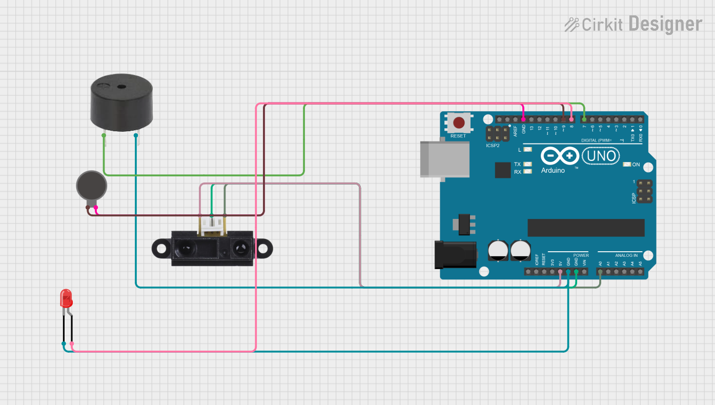
Circuit Documentation
Summary
This circuit is designed around an Arduino UNO microcontroller and includes a Sharp IR Sensor, a vibration motor, a buzzer, and a red two-pin LED. The Arduino UNO is used to read the analog value from the IR sensor and control the other components based on the sensor's readings. The circuit is likely intended for proximity detection or a similar application where the distance to an object is monitored, and feedback is provided via the buzzer, LED, and vibration motor.
Component List
Arduino UNO
- Description: A microcontroller board based on the ATmega328P.
- Purpose: Acts as the central processing unit of the circuit, reading sensor data and controlling the output devices (LED, buzzer, and vibration motor).
Vibration Motor
- Description: A small motor that vibrates when powered.
- Purpose: Provides haptic feedback.
Sharp IR Sensor
- Description: An infrared distance measuring sensor.
- Purpose: Measures the distance to an object and provides this information to the Arduino.
Buzzer
- Description: An electronic buzzer that emits sound when powered.
- Purpose: Provides audible feedback.
LED: Two Pin (red)
- Description: A basic red LED.
- Purpose: Provides visual feedback.
Wiring Details
Arduino UNO
- 5V connected to Sharp IR Sensor VCC
- GND connected to Sharp IR Sensor GND, Vibration Motor -, Buzzer GND, and LED cathode
- A0 connected to Sharp IR Sensor Pin
- D9 connected to Vibration Motor +
- D8 connected to LED anode
- D7 connected to Buzzer PIN
Vibration Motor
- + connected to Arduino UNO D9
- - connected to Arduino UNO GND
Sharp IR Sensor
- VCC connected to Arduino UNO 5V
- GND connected to Arduino UNO GND
- Pin connected to Arduino UNO A0
Buzzer
- PIN connected to Arduino UNO D7
- GND connected to Arduino UNO GND
LED: Two Pin (red)
- anode connected to Arduino UNO D8
- cathode connected to Arduino UNO GND
Documented Code
// Define pin connections
const int irSensorPin = A0;
const int buzzerPin = 7;
const int ledPin = 8;
const int vibrationMotorPin = 9;

// Define the number of readings to keep track of for averaging
const int numReadings = 10;
int irReadings[numReadings]; // Array to store the IR sensor readings
int readIndex = 0; // Index of the current reading
int totalIR = 0; // Sum of the readings
int averageIR = 0; // Average of the readings

void setup() {
  // Initialize the output pins
  pinMode(buzzerPin, OUTPUT);
  pinMode(ledPin, OUTPUT);
  pinMode(vibrationMotorPin, OUTPUT);

  // Start serial communication
  Serial.begin(9600);

  // Initialize all readings to 0
  for (int i = 0; i < numReadings; i++) {
    irReadings[i] = 0;
  }
}

void loop() {
  // Read the value from the IR sensor
  int irValue = analogRead(irSensorPin);

  // Update the readings array
  totalIR = totalIR - irReadings[readIndex];
  irReadings[readIndex] = irValue;
  totalIR = totalIR + irReadings[readIndex];
  readIndex = (readIndex + 1) % numReadings;

  // Calculate the average
  averageIR = totalIR / numReadings;

  // Print the average IR value to the serial monitor
  Serial.print("Average IR: "); Serial.println(averageIR);

  // Drowsiness detection based on average values
  if (averageIR < 300) { // Example threshold, adjust as needed
    // If the average IR value is below the threshold, activate the outputs
    digitalWrite(buzzerPin, HIGH);
    digitalWrite(ledPin, HIGH);
    digitalWrite(vibrationMotorPin, HIGH);
  } else {
    // If the average IR value is above the threshold, deactivate the outputs
    digitalWrite(buzzerPin, LOW);
    digitalWrite(ledPin, LOW);
    digitalWrite(vibrationMotorPin, LOW);
  }

  // Delay for a short period of time
  delay(100); // Adjust delay as needed
}
This code is designed to read the analog value from the IR sensor and calculate an average value over a series of readings. If the average value falls below a certain threshold, it activates the buzzer, LED, and vibration motor to alert the user. The delay at the end of the loop controls the rate at which the readings are taken.