Cirkit Designer
Your all-in-one circuit design IDE
Home /
Project Documentation
Arduino UNO Controlled DC Motor with RTC and Keypad Interface
Circuit Documentation
Summary
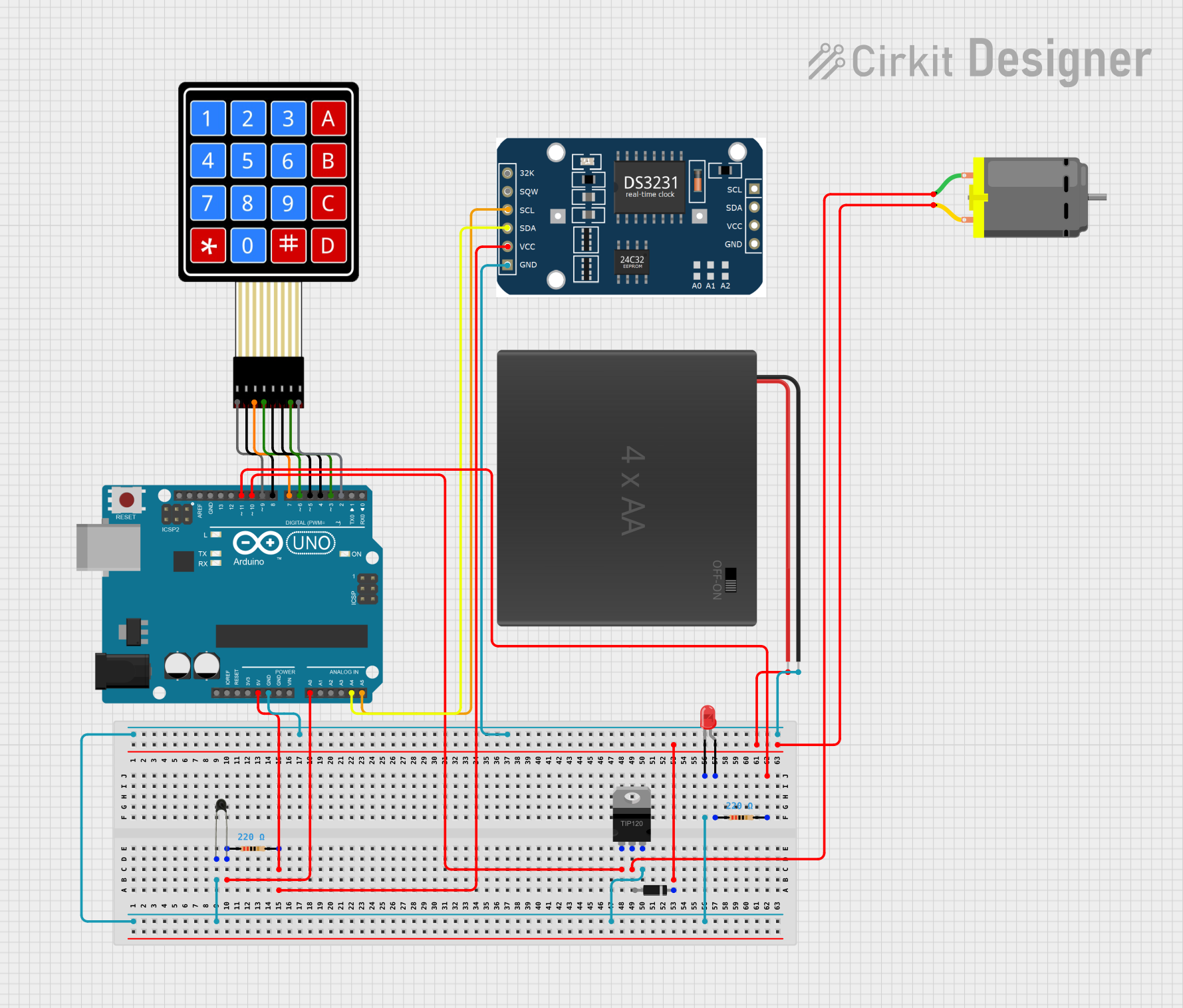
This document provides a detailed overview of a circuit designed to interface various components with an Arduino UNO microcontroller. The circuit includes a DC motor controlled by a TIP120 Darlington Transistor, a diode for back EMF protection, resistors, an NTC thermistor, a 4x4 membrane matrix keypad, an RTC module, and a red LED indicator. The Arduino UNO serves as the central processing unit, managing inputs from the keypad and NTC, controlling the DC motor, and interfacing with the RTC module. Power is supplied by a 4xAA battery pack.
Component List
DC Motor
- Description: A motor that converts DC electrical power into mechanical rotation.
- Purpose: To perform mechanical work when activated by the circuit.
TIP120 Hi-Current Darlington Transistor
- Description: A high-current, high-voltage Darlington transistor used for switching applications.
- Purpose: To control the power supplied to the DC motor from the Arduino UNO.
Diode
- Description: A semiconductor device that allows current to flow in one direction only.
- Purpose: To protect the circuit from reverse voltage spikes generated by the DC motor.
Resistor (220 Ohms)
- Description: A passive two-terminal electrical component that implements electrical resistance.
- Purpose: To limit current flow, used in the LED and NTC circuits.
NTC (Negative Temperature Coefficient)
- Description: A thermistor with a resistance that decreases as the temperature increases.
- Purpose: To measure temperature changes in the environment.
4X4 Membrane Matrix Keypad
- Description: A 16-button interface that provides user input to the microcontroller.
- Purpose: To allow user interaction with the circuit for control or data entry.
RTC (Real-Time Clock) MODULE
- Description: A real-time clock module for keeping track of the current time.
- Purpose: To provide accurate timekeeping for time-sensitive applications.
Arduino UNO
- Description: A microcontroller board based on the ATmega328P.
- Purpose: To serve as the central processing unit of the circuit, executing the embedded code and controlling the components.
4xAA Battery Pack
- Description: A power source consisting of four AA batteries in series.
- Purpose: To provide the necessary voltage and current to power the circuit.
LED: Two Pin (red)
- Description: A red light-emitting diode.
- Purpose: To serve as an indicator light within the circuit.
Wiring Details
DC Motor
- Connected to the COLLECTOR of the TIP120 Transistor.
- The other terminal is connected to the POSITIVE terminal of the 4xAA battery pack.
TIP120 Hi-Current Darlington Transistor
- BASE connected to Arduino UNO pin D10.
- COLLECTOR connected to one terminal of the DC Motor.
- EMITTER connected to the GROUND net.
Diode
- CATHODE connected to the POSITIVE terminal of the 4xAA battery pack.
- ANODE connected to one terminal of the DC Motor.
Resistor (220 Ohms)
- One terminal connected to Arduino UNO pin A0 and the other terminal to the NTC.
- Another 220 Ohm resistor is connected between the Arduino UNO pin D11 and the anode of the red LED.
NTC
- One terminal connected to a 220 Ohm resistor and Arduino UNO pin A0.
- The other terminal connected to the GROUND net.
4X4 Membrane Matrix Keypad
- R1 connected to Arduino UNO pin D9.
- R2 connected to Arduino UNO pin D8.
- R3 connected to Arduino UNO pin D7.
- R4 connected to Arduino UNO pin D6.
- C1 connected to Arduino UNO pin D5.
- C2 connected to Arduino UNO pin D4.
- C3 connected to Arduino UNO pin D3.
- C4 connected to Arduino UNO pin D2.
RTC MODULE
- 32k, SQW pins not connected.
- SCL connected to Arduino UNO pin A5.
- SDA connected to Arduino UNO pin A4.
- VCC connected to the 5V net.
- GND connected to the GROUND net.
Arduino UNO
- GND pins connected to the GROUND net.
- 5V pin connected to the 5V net.
- Digital and analog pins connected as specified in the wiring details for each component.
4xAA Battery Pack
- POSITIVE terminal connected to the anode of the Diode and the DC Motor.
- NEGATIVE terminal connected to the GROUND net.
LED: Two Pin (red)
- CATHODE connected to the GROUND net.
- ANODE connected to a 220 Ohm resistor and Arduino UNO pin D11.
Documented Code
Arduino UNO Code (sketch.ino)
void setup() {
  // put your setup code here, to run once:

}

void loop() {
  // put your main code here, to run repeatedly:

}
Additional Notes
- The provided code is a template and does not contain any functional implementation. It needs to be populated with the logic to control the circuit components based on the requirements.
- The
setup()function is intended for initialization code that runs once at the start, such as pin mode declarations. - The
loop()function contains the main logic that the Arduino will execute repeatedly. - The actual implementation should include code to read inputs from the NTC and keypad, control the DC motor via the TIP120 transistor, and interface with the RTC module.