
Circuit Documentation
Summary
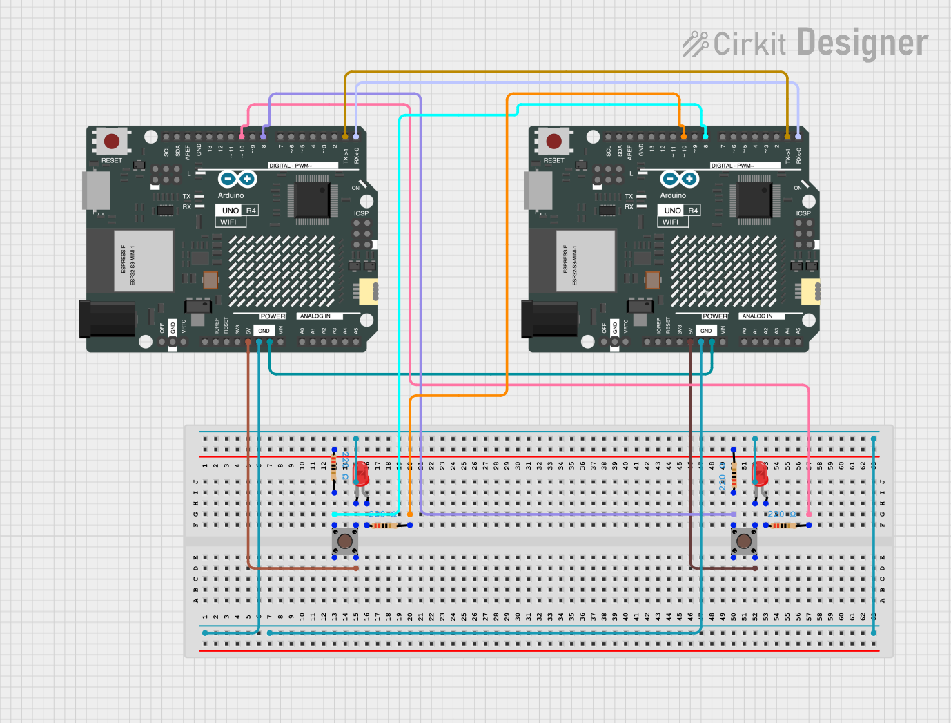
The circuit in question is designed around two Arduino UNO R4 WiFi microcontrollers, which are interconnected and control two red LEDs through pushbuttons. The LEDs are connected with resistors to limit the current and protect the LEDs. The pushbuttons are used to toggle the state of the LEDs and send a signal to the microcontrollers. The microcontrollers communicate with each other via serial communication, and the state of the LEDs can be changed through this communication as well.
Component List
Microcontrollers
- Arduino UNO R4 WiFi: A microcontroller board based on the ATmega328, with integrated WiFi capabilities. It has a variety of digital and analog I/O pins.
LEDs
- LED: Two Pin (red): A basic red light-emitting diode that emits red light when a forward current passes through it.
Pushbuttons
- Pushbutton: A simple switch mechanism for controlling some aspect of a machine or a process. Buttons are typically made out of hard material, usually plastic or metal.
Resistors
- Resistor: A passive two-terminal electrical component that implements electrical resistance as a circuit element. In this circuit, 220-ohm resistors are used to limit the current through the LEDs.
Wiring Details
Arduino UNO R4 WiFi
- 5V: Connected to the 'Pin 1 (in)' of both pushbuttons.
- GND: Common ground shared with the other Arduino UNO R4 WiFi, both pushbuttons, and both LEDs.
- D0/RX: Connected to the D0/RX of the other Arduino UNO R4 WiFi for serial communication.
- D1/TX: Connected to the D1/TX of the other Arduino UNO R4 WiFi for serial communication.
- D8: Connected to 'Pin 4 (out)' of one pushbutton through a 220-ohm resistor.
- D10: Connected to 'Pin 4 (out)' of the other pushbutton through a 220-ohm resistor.
LED: Two Pin (red)
- Cathode: Connected to the common ground.
- Anode: Connected to the 'pin1' of a 220-ohm resistor.
Pushbutton
- Pin 1 (in): Connected to the 5V pin of the corresponding Arduino UNO R4 WiFi.
- Pin 2 (in): Connected to the common ground.
- Pin 4 (out): Connected to the digital pin (D8 or D10) of the corresponding Arduino UNO R4 WiFi through a 220-ohm resistor.
Resistor
- Pin1: Connected to the anode of the corresponding LED.
- Pin2: Connected to the digital pin (D8 or D10) of the corresponding Arduino UNO R4 WiFi.
Documented Code
Arduino UNO R4 WiFi (First Microcontroller)
unsigned long prev = 0;
const int LED = 10;
const int button = 8;
int ledOn = HIGH;
bool buttonPressed = false;

void setup() {
    pinMode(LED, OUTPUT);
    pinMode(button, INPUT_PULLUP);
    digitalWrite(LED, ledOn);
    Serial.begin(9600);
}

void loop() {
    if (digitalRead(button) == LOW && !buttonPressed) {
        unsigned long curr = millis();
        if (curr - prev > 100) {
            buttonPressed = true;
            prev = curr;
            Serial.write('L');
        }
    }
    else if (digitalRead(button) == HIGH && buttonPressed) {
        buttonPressed = false; // Reset button state
    }

    if (Serial.available() > 0) {
        Serial.read();
        ledOn = !ledOn; // Toggle LED
        digitalWrite(LED, ledOn); // Update LED
    }
}
Arduino UNO R4 WiFi (Second Microcontroller)
unsigned long prev = 0;
const int LED = 10;
const int button = 8;
int ledOn = HIGH;
bool buttonPressed = false;

void setup() {
  pinMode(LED, OUTPUT);
  pinMode(button, INPUT_PULLUP);
  digitalWrite(LED, ledOn);
  Serial.begin(9600);
}

void loop() {
  if (digitalRead(button) == LOW && !buttonPressed) {
    unsigned long curr = millis();
    if (curr - prev > 100) {
      buttonPressed = true;
      prev = curr;
      Serial.write('L');
    }
  }
  else if (digitalRead(button) == HIGH && buttonPressed) {
    buttonPressed = false; // Reset button state
  }

  if (Serial.available() > 0) {
    Serial.read();
    ledOn = !ledOn; // Toggle LED
    digitalWrite(LED, ledOn); // Update LED
  }
}
This concludes the documentation for the provided circuit design. The code for both microcontrollers is identical and is designed to toggle the state of an LED when a button is pressed and also when a signal is received via serial communication.