
Circuit Documentation
Summary
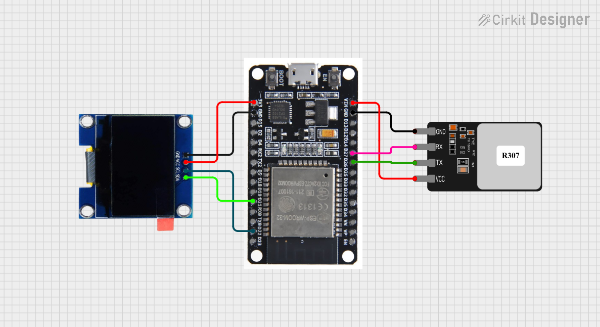
The circuit in question is designed to interface an ESP32 microcontroller with a Fingerprint Scanner and an OLED 1.3" display. The ESP32 serves as the central processing unit, handling data from the Fingerprint Scanner and outputting information to the OLED display. The Fingerprint Scanner is used for biometric identification, and the OLED display provides a visual interface for the user.
Component List
ESP32
- Description: A microcontroller with Wi-Fi and Bluetooth capabilities, featuring a variety of digital and analog I/O pins.
- Purpose: Acts as the central processing unit for the circuit, managing data communication between the Fingerprint Scanner, OLED display, and potentially other peripherals or networks.
Fingerprint Scanner
- Description: A biometric sensor that captures fingerprints for identification purposes.
- Purpose: Provides biometric authentication by capturing and transmitting fingerprint data to the ESP32 for processing.
OLED 1.3" Display
- Description: A small display with organic light-emitting diodes, capable of showing graphics and text.
- Purpose: Displays information and feedback to the user, controlled by the ESP32.
Comment
- Description: A placeholder for additional notes or comments within the circuit design.
- Purpose: To provide annotations or explanations within the circuit design, not an actual physical component.
Wiring Details
ESP32
- EN: Not connected in this circuit.
- VP: Not connected in this circuit.
- VN: Not connected in this circuit.
- D34-D25, D14-D13, D15, D2, D4, RX2, TX2, D5, D18, D19, BOOT: Not connected in this circuit.
- GND: Connected to the GND pins of the Fingerprint Scanner and OLED display.
- VIN: Supplies power to the Fingerprint Scanner.
- 3V3: Supplies power to the OLED display.
- D26: Receives TX signal from the Fingerprint Scanner.
- D27: Sends RX signal to the Fingerprint Scanner.
- D21 (SDA): Connected to the SDA pin of the OLED display for I2C data communication.
- D22 (SCL): Connected to the SCL pin of the OLED display for I2C clock signal.
Fingerprint Scanner
- VCC: Powered by the VIN pin of the ESP32.
- TX: Transmits data to the D26 pin of the ESP32.
- RX: Receives data from the D27 pin of the ESP32.
- GND: Common ground with the ESP32.
OLED 1.3" Display
- VCC: Powered by the 3V3 pin of the ESP32.
- GND: Common ground with the ESP32.
- SCL: Connected to the D22 pin of the ESP32 for I2C clock signal.
- SDA: Connected to the D21 pin of the ESP32 for I2C data communication.
Documented Code
No code has been provided for the microcontrollers in the circuit. Therefore, this section is currently empty. When code is available, it should be documented here with explanations for each function and routine, as well as any relevant algorithms or communication protocols used.