
Arduino Mega 2560 and INA219 Sensor for Current and Voltage Measurement
View and Edit Project In Cirkit Designer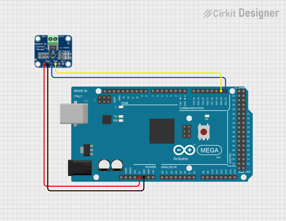
Circuit Documentation
Summary
This document describes a circuit that connects an Arduino Mega 2560 to an INA219 sensor. The INA219 sensor is used for current and voltage measurement and communicates with the Arduino via the I2C protocol. The Arduino reads the sensor data and prints it to the Serial Monitor.
Component List
INA219
- Description: The INA219 is a current and voltage sensor that communicates via the I2C protocol.
- Pins: VCC, GND, SCL, SDA, VIN -, VIN +
Arduino Mega 2560
- Description: The Arduino Mega 2560 is a microcontroller board based on the ATmega2560. It has 54 digital input/output pins, 16 analog inputs, and 4 UARTs (hardware serial ports).
- Pins: IOREF, RESET, 3V3, 5V, GND, VIN, A0-A15, D21/SCL, D20/SDA, D19/RX1, D18/TX1, D17 PWM/RX2, D16 PWM/TX2, D15/RX3, D14/TX3, D0 RX0, D1 TX0, D2 PWM, D3 PWM, D4 PWM, D5 PWM, D6 PWM, D7 PWM, D8 PWM, D9 PWM, D10 PWM, D11 PWM, D12 PWM, D13 PWM, AREF, SDA, SCL, D52, D50, D48, D46, D44, D42, D40, D38, D36, D34, D32, D30, D28, D26, D24, D22, D53, D51, D49, D47, D45, D43, D41, D39, D37, D35, D33, D31, D29, D27, D25, D23
Wiring Details
INA219
- VCC: Connected to Arduino Mega 2560 5V
- GND: Connected to Arduino Mega 2560 GND
- SCL: Connected to Arduino Mega 2560 D21/SCL
- SDA: Connected to Arduino Mega 2560 D20/SDA
Arduino Mega 2560
- 5V: Connected to INA219 VCC
- GND: Connected to INA219 GND
- D21/SCL: Connected to INA219 SCL
- D20/SDA: Connected to INA219 SDA
Code
/*
 * This Arduino sketch connects an Arduino Mega 2560 to an INA219 sensor.
 * The INA219 sensor is used for current and voltage measurement.
 * The sensor communicates with the Arduino via the I2C protocol.
 */

#include <Wire.h>
#include <Adafruit_INA219.h>

Adafruit_INA219 ina219;

void setup() {
  // Initialize serial communication at 9600 baud rate
  Serial.begin(9600);
  while (!Serial) {
    // Wait for serial port to connect. Needed for native USB port only
  }

  // Initialize the INA219 sensor
  if (!ina219.begin()) {
    Serial.println("Failed to find INA219 chip");
    while (1) { delay(10); }
  }
  Serial.println("INA219 sensor initialized");
}

void loop() {
  // Read current in mA
  float current_mA = ina219.getCurrent_mA();
  // Read bus voltage in V
  float bus_voltage_V = ina219.getBusVoltage_V();
  // Read shunt voltage in mV
  float shunt_voltage_mV = ina219.getShuntVoltage_mV();
  // Read power in mW
  float power_mW = ina219.getPower_mW();

  // Print the readings to the Serial Monitor
  Serial.print("Current: ");
  Serial.print(current_mA);
  Serial.println(" mA");

  Serial.print("Bus Voltage: ");
  Serial.print(bus_voltage_V);
  Serial.println(" V");

  Serial.print("Shunt Voltage: ");
  Serial.print(shunt_voltage_mV);
  Serial.println(" mV");

  Serial.print("Power: ");
  Serial.print(power_mW);
  Serial.println(" mW");

  // Wait for 2 seconds before the next reading
  delay(2000);
}
This code initializes the INA219 sensor and reads current, bus voltage, shunt voltage, and power. The readings are printed to the Serial Monitor every 2 seconds.