
Circuit Documentation
Summary
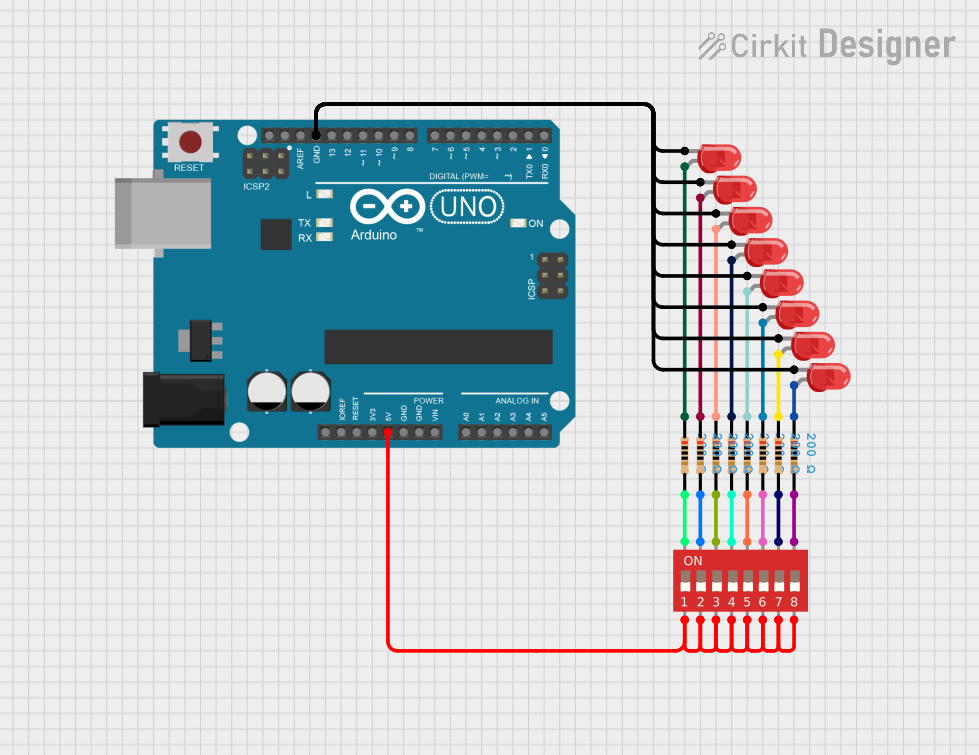
This circuit utilizes an Arduino UNO microcontroller to control a series of LED indicators based on the state of an 8-position DIP switch. The circuit includes multiple resistors to limit current to the LEDs and ensure proper operation. The DIP switch allows for user input, which can be read by the Arduino to determine the state of each switch position.
Component List
1. Arduino UNO
- Description: A microcontroller board based on the ATmega328P.
- Purpose: Acts as the main control unit for the circuit, processing inputs from the DIP switch and controlling the LEDs.
2. DIP Switch (8 Position)
- Description: A manual switch that allows the user to select one or more positions.
- Purpose: Provides user input to the Arduino, allowing for different configurations based on the switch positions.
3. Resistor
- Description: A passive electrical component that limits current flow.
- Purpose: Used in series with the LEDs to prevent excessive current that could damage them. Each resistor has a resistance of 200 Ohms.
4. LED Two Pin (Red)
- Description: A two-pin light-emitting diode that emits red light when current flows through it.
- Purpose: Serves as an indicator that lights up based on the state of the DIP switch and the control logic from the Arduino.
Wiring Details
Arduino UNO
5V connected to:
- DIP Switch (3a)
- DIP Switch (4a)
- DIP Switch (5a)
- DIP Switch (6a)
- DIP Switch (7a)
- DIP Switch (8a)
- DIP Switch (1a)
- DIP Switch (2a)
GND connected to:
- LED (Cathode) 1
- LED (Cathode) 2
- LED (Cathode) 3
- LED (Cathode) 4
- LED (Cathode) 5
- LED (Cathode) 6
- LED (Cathode) 7
- LED (Cathode) 8
DIP Switch (8 Position)
1b connected to:
- Resistor (pin2)
2b connected to:
- Resistor (pin2)
3b connected to:
- Resistor (pin2)
4b connected to:
- Resistor (pin2)
5b connected to:
- Resistor (pin2)
6b connected to:
- Resistor (pin2)
7b connected to:
- Resistor (pin2)
8b connected to:
- Resistor (pin2)
Resistor
Resistor 1 (200 Ohms)
- pin1 connected to:
- LED (Anode) 1
- pin1 connected to:
Resistor 2 (200 Ohms)
- pin1 connected to:
- LED (Anode) 2
- pin1 connected to:
Resistor 3 (200 Ohms)
- pin1 connected to:
- LED (Anode) 3
- pin1 connected to:
Resistor 4 (200 Ohms)
- pin1 connected to:
- LED (Anode) 4
- pin1 connected to:
Resistor 5 (200 Ohms)
- pin1 connected to:
- LED (Anode) 5
- pin1 connected to:
Resistor 6 (200 Ohms)
- pin1 connected to:
- LED (Anode) 6
- pin1 connected to:
Resistor 7 (200 Ohms)
- pin1 connected to:
- LED (Anode) 7
- pin1 connected to:
Resistor 8 (200 Ohms)
- pin1 connected to:
- LED (Anode) 8
- pin1 connected to:
LED Two Pin (Red)
LED 1
- Cathode connected to:
- GND
- Anode connected to:
- Resistor 1 (pin1)
- Cathode connected to:
LED 2
- Cathode connected to:
- GND
- Anode connected to:
- Resistor 2 (pin1)
- Cathode connected to:
LED 3
- Cathode connected to:
- GND
- Anode connected to:
- Resistor 3 (pin1)
- Cathode connected to:
LED 4
- Cathode connected to:
- GND
- Anode connected to:
- Resistor 4 (pin1)
- Cathode connected to:
LED 5
- Cathode connected to:
- GND
- Anode connected to:
- Resistor 5 (pin1)
- Cathode connected to:
LED 6
- Cathode connected to:
- GND
- Anode connected to:
- Resistor 6 (pin1)
- Cathode connected to:
LED 7
- Cathode connected to:
- GND
- Anode connected to:
- Resistor 7 (pin1)
- Cathode connected to:
LED 8
- Cathode connected to:
- GND
- Anode connected to:
- Resistor 8 (pin1)
- Cathode connected to:
Documented Code
Arduino Code
void setup() {
  // put your setup code here, to run once:

}

void loop() {
  // put your main code here, to run repeatedly:

}
Documentation
This section is reserved for additional documentation or notes related to the circuit and its operation.