Cirkit Designer
Your all-in-one circuit design IDE
Home /
Project Documentation
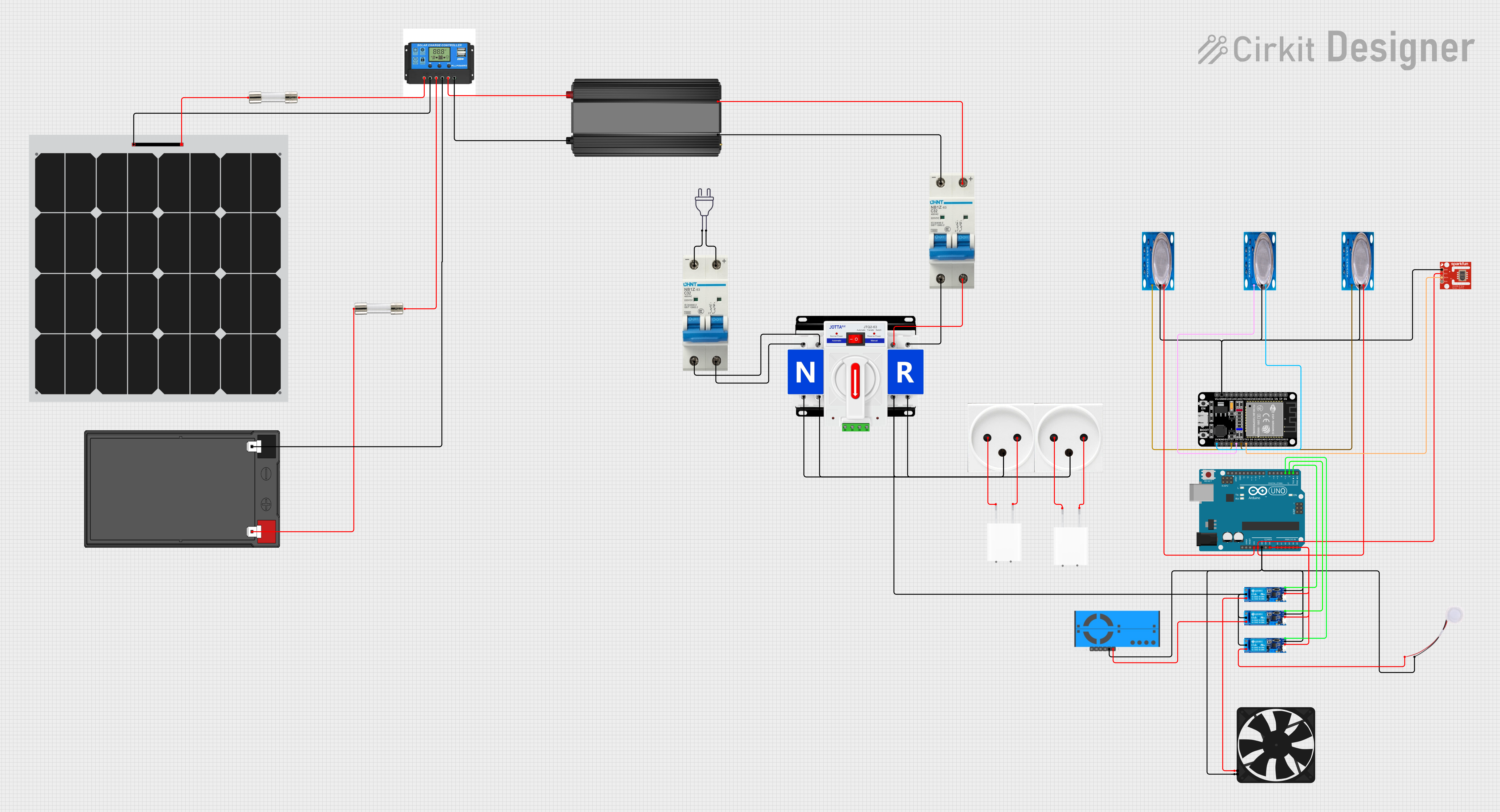
Solar-Powered Environmental Monitoring and Control System with Automatic Transfer Switch and IoT Capability
Circuit Documentation
Summary
This document provides a detailed overview of a power management and environmental sensing circuit. The circuit is designed to handle dual power sources, manage power distribution through fuses and circuit breakers, and control power to various devices such as a humidifier, fan, and air quality sensor. It also includes microcontrollers for monitoring and control purposes.
Component List
Power Sources
- 12v 7ah Battery: A rechargeable battery providing a 12V power supply.
- Solar Panel: A photovoltaic panel used to convert solar energy into electrical power.
Power Management
- Fuse: A safety device that protects the circuit from overcurrent by breaking the connection when current exceeds a certain threshold.
- Circuit Breaker: An automatically operated electrical switch designed to protect an electrical circuit from damage caused by excess current.
- Dual Power Automatic Transfer Switch: A device that switches between two power sources to ensure continuous power supply.
- Charge Controller: Regulates the voltage and current coming from the solar panels going to the battery.
- Power Inverter: Converts DC power from the battery into AC power for household devices.
Power Distribution
- Power Outlet (IL): An interface for electrical devices to connect to the power supply.
- 5V Adapter: Converts AC power from the power outlet to a 5V DC output.
Control and Sensing
- Arduino UNO: A microcontroller board based on the ATmega328P, used for controlling relays and reading sensor data.
- ESP32 (30 pin): A microcontroller with Wi-Fi and Bluetooth capabilities, used for processing and transmitting sensor data.
- MQ-5 Gas Sensor: A gas sensor used for detecting levels of gas in the air.
- SHT1x-Breakout: A sensor for measuring humidity and temperature.
- PM2.5 Air Quality Sensor and Breadboard Adapter Kit - PMS5003: A sensor for measuring particulate matter in the air.
Actuators
- Humidifier: A device that adds moisture to the air.
- Fan: A device that creates airflow.
- Relay Module 5v-30v: An electrically operated switch that controls the power to the humidifier and fan.
Wiring Details
Power Sources
12v 7ah Battery
12v +connected to Fuse (Terminal 1)12v -connected to Charge Controller (Battery Negative)
Solar Panel
+connected to Fuse (Terminal 1)-connected to Charge Controller (Solar Negative)
Power Management
Fuse
Terminal 1connected to 12v 7ah Battery (12v +) and Solar Panel (+)Terminal 2connected to Charge Controller (Battery Positive) and Charge Controller (Solar Positive)
Circuit Breaker
+connected to Dual Power Automatic Transfer Switch (+) and Power Inverter (+)-connected to Dual Power Automatic Transfer Switch (-) and Power Inverter (-)
Dual Power Automatic Transfer Switch
+connected to Circuit Breaker (+) and Relay Module 5v-30v (common contact)-connected to Circuit Breaker (-) and Power Outlet (IL) (GND)
Charge Controller
Solar Positiveconnected to Fuse (Terminal 2)Solar Negativeconnected to Solar Panel (-)Battery Positiveconnected to Fuse (Terminal 2)Battery Negativeconnected to 12v 7ah Battery (12v -)Load Positiveconnected to Power Inverter (+)Load Negativeconnected to Power Inverter (-)
Power Inverter
+connected to Charge Controller (Load Positive) and Circuit Breaker (+)-connected to Charge Controller (Load Negative) and Circuit Breaker (-)
Power Distribution
Power Outlet (IL)
Nconnected to 5V Adapter (AC In 1)Lconnected to 5V Adapter (AC In 2)GNDconnected to Dual Power Automatic Transfer Switch (-) and Relay Module 5v-30v (common contact)
5V Adapter
AC In 1connected to Power Outlet (IL) (N)AC In 2connected to Power Outlet (IL) (L)5Vconnected to Relay Module 5v-30v (normally closed)GNDconnected to Relay Module 5v-30v (V-)
Control and Sensing
Arduino UNO
3.3Vconnected to MQ-5 Gas Sensor (VCC)5Vconnected to SHT1x-Breakout (VCC) and MQ-5 Gas Sensor (VCC)GNDconnected to Relay Module 5v-30v (V-)Vinconnected to Relay Module 5v-30v (V+)D1connected to Relay Module 5v-30v (trigger)D2connected to Relay Module 5v-30v (trigger)D3connected to Relay Module 5v-30v (trigger)
ESP32 (30 pin)
GNDconnected to MQ-5 Gas Sensor (GND)3V3connected to MQ-5 Gas Sensor (VCC)TX2connected to SHT1x-Breakout (DATA)RX2connected to MQ-5 Gas Sensor (Analog out)D4connected to MQ-5 Gas Sensor (Analog out)D2connected to MQ-5 Gas Sensor (Analog out)
Actuators
Humidifier
5Vconnected to Relay Module 5v-30v (normally closed)GNDconnected to Relay Module 5v-30v (V-)
Fan
5Vconnected to Relay Module 5v-30v (normally closed)GNDconnected to Relay Module 5v-30v (V-)
Relay Module 5v-30v
common contactconnected to Dual Power Automatic Transfer Switch (+)normally open(not connected)normally closedconnected to Humidifier (5V), Fan (5V), and PM2.5 Air Quality Sensor (VCC)triggerconnected to Arduino UNO (D1, D2, D3)V-connected to 5V Adapter (GND)V+connected to Arduino UNO (Vin)
Documented Code
Arduino UNO Code (sketch.ino)
void setup() {
  // put your setup code here, to run once:

}

void loop() {
  // put your main code here, to run repeatedly:

}
Additional Notes
- The code for the Arduino UNO is currently a template with empty
setup()andloop()functions. These functions need to be populated with the logic to control the relay modules based on sensor inputs and possibly communicate with the ESP32 for more complex tasks. - The ESP32 code is not provided in the input and should be developed to handle sensor data processing and wireless communication tasks.
- The documentation file for the Arduino UNO is empty and should be filled with relevant information about the code, including the logic behind the control algorithms and the interaction with other components in the circuit.