Cirkit Designer
Your all-in-one circuit design IDE
Home /
Project Documentation
Arduino Nano Automated Plant Watering System with Soil Moisture Sensing and OLED Display

Circuit Documentation
Summary
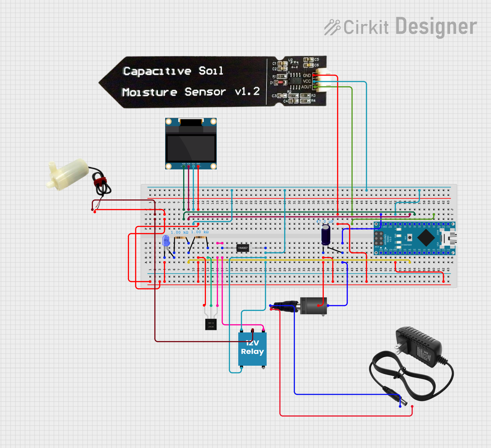
This circuit is designed to control a 5V mini water pump and monitor soil moisture levels using an Arduino Nano as the central microcontroller. The circuit includes a 12V relay to switch the water pump, a capacitive soil moisture sensor for detecting moisture levels, an OLED display for output, and various other components such as resistors, a transistor, a diode, and capacitors for power stabilization and signal interfacing.
Component List
Arduino Nano
- Microcontroller board based on the ATmega328P
- It has a variety of digital and analog I/O pins.
Electrolytic Capacitor
- Capacitance: 47 µF (microfarads)
- Used for power supply filtering.
Power Jack
- Connects the external power supply to the circuit.
2.1mm DC Barrel Jack
- Used to connect an external power source with a barrel connector.
12V Relay
- Electromechanical switch used to control the water pump.
0.96" OLED
- Small display for showing information such as soil moisture levels.
Resistor (1 kΩ)
- Two resistors with a resistance of 1 kΩ each, used for current limiting and voltage division.
BC547
- NPN Bipolar Junction Transistor (BJT) used for signal amplification or switching.
1N4007 Rectifier Diode
- Standard diode used for protecting the circuit from reverse voltage.
Capacitive Soil Moisture Sensor V1.2
- Measures the moisture content in the soil.
LED: Two Pin (blue)
- Blue light-emitting diode used as an indicator.
5V Mini Water Pump
- A small pump for moving water, controlled by the relay.
12V Power Supply
- Provides the necessary power for the circuit.
Wiring Details
Arduino Nano
GNDconnected to the common ground net.5Vconnected to the OLED VDD, relay VCC, and soil moisture sensor VCC.VINconnected to the positive side of the electrolytic capacitor and the center pin of the DC barrel jack.A0connected to the AOUT pin of the soil moisture sensor.A4connected to the SDA pin of the OLED.A5connected to the SCK pin of the OLED.D4connected to one end of a 1 kΩ resistor.
Electrolytic Capacitor
-(negative) connected to the common ground net.+(positive) connected to the Arduino Nano VIN.
Power Jack
POSITIFconnected to the positive terminal of the 12V power supply.NEGATIFconnected to the negative terminal of the 12V power supply.
2.1mm DC Barrel Jack
switchconnected to the common ground net.centerconnected to the positive side of the electrolytic capacitor and Arduino Nano VIN.
12V Relay
+connected to the OLED VDD and Arduino Nano 5V.-connected to the collector of the BC547 transistor and the anode of the 1N4007 diode.Cconnected to the positive pin of the water pump.NCconnected to the OLED VDD and Arduino Nano 5V.NOnot connected in this circuit.
0.96" OLED
GNDconnected to the common ground net.VDDconnected to the Arduino Nano 5V, relay VCC, and soil moisture sensor VCC.SCKconnected to the Arduino Nano A5.SDAconnected to the Arduino Nano A4.
Resistor (1 kΩ)
- One resistor connected between Arduino Nano D4 and the base of the BC547 transistor.
- The other resistor connected between the anode of the LED and the common ground net.
BC547
collectorconnected to the relay-and the cathode of the 1N4007 diode.baseconnected to one end of a 1 kΩ resistor.Emitterconnected to the common ground net.
1N4007 Rectifier Diode
Cathodeconnected to the OLED VDD and relay VCC.Anodeconnected to the collector of the BC547 transistor.
Capacitive Soil Moisture Sensor V1.2
GNDconnected to the common ground net.VCCconnected to the OLED VDD and Arduino Nano 5V.AOUTconnected to the Arduino Nano A0.
LED: Two Pin (blue)
cathodeconnected to the common ground net.anodeconnected to one end of a 1 kΩ resistor.
5V Mini Water Pump
positive pinconnected to the relay C.negative pinconnected to the common ground net.
12V Power Supply
+connected to the power jack POSITIF.-connected to the power jack NEGATIF.
Documented Code
Arduino Nano - sketch.ino
void setup() {
  // put your setup code here, to run once:

}

void loop() {
  // put your main code here, to run repeatedly:

}
Arduino Nano - documentation.txt
(No additional documentation provided for the code)
(Note: The code provided is a template and does not contain any functional code. It will need to be populated with the logic required to read the soil moisture sensor, control the OLED display, and manage the water pump via the relay.)