ESP32-Based Audio Player with SD Card Storage and Amplification
Circuit Documentation
Summary
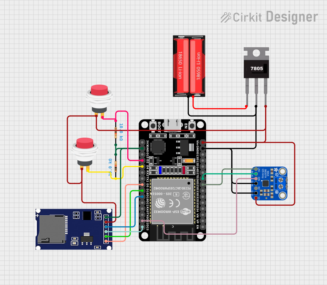
This circuit integrates an ESP32 microcontroller with various peripherals including a digital audio amplifier (Adafruit MAX98357A), an SD card module for data storage, and user input switches. The circuit is powered by a 18650 Li-Ion battery, regulated to 5V by a 7805 voltage regulator. The ESP32 facilitates audio output through the Adafruit MAX98357A and data logging or retrieval through the SD card module. User interaction is managed via two push switches, each debounced with a 10kΩ resistor.
Component List
ESP32 (30 pin)
- Description: A 30-pin microcontroller with Wi-Fi and Bluetooth capabilities.
- Pins: EN, VP, VN, D34, D35, D32, D33, D25, D26, D27, D14, D12, D13, GND, Vin, D23, D22, TX0, RX0, D21, D19, D18, D5, TX2, RX2, D4, D2, D15, 3V3
2Pin Push Switch
- Description: A simple push-button switch used for user input.
- Pins: Input +, Output +
Resistor (10kΩ)
- Description: A resistor with a resistance of 10kΩ, used for debouncing switches.
- Pins: pin1, pin2
SDmodule
- Description: An SD card module for data storage and retrieval.
- Pins: CS, SCK, MOSI, MISO, VCC, GND
7805 Voltage Regulator
- Description: A voltage regulator that outputs a stable 5V from a higher voltage input.
- Pins: Vin, Gnd, Vout
18650 Li-Ion Battery
- Description: A rechargeable lithium-ion battery.
- Pins: Positive, Negative
Adafruit MAX98357A
- Description: A digital audio amplifier for use with I2S digital audio signals.
- Pins: VIN, GND, SD_MODE, GAIN, DIN, BCLK, LRCLK, VO+, VO-
Wiring Details
ESP32 (30 pin)
- D25 connected to Adafruit MAX98357A LRCLK
- D26 connected to Adafruit MAX98357A BCLK
- GND connected to common ground net
- Vin connected to 7805 Vout
- D23 connected to SDmodule MOSI
- D22 connected to Adafruit MAX98357A DIN
- D19 connected to SDmodule MISO
- D18 connected to SDmodule SCK
- D5 connected to SDmodule CS
- D4 connected to one side of the debounced push switch
- D2 connected to the other debounced push switch
2Pin Push Switch
- Input + connected to 7805 Vout
- Output + connected to ESP32 D4 or D2 through a 10kΩ resistor
Resistor (10kΩ)
- One pin connected to 2Pin Push Switch Output +
- The other pin connected to ESP32 D4 or D2 and to common ground net
SDmodule
- VCC connected to 7805 Vout
- MOSI connected to ESP32 D23
- MISO connected to ESP32 D19
- SCK connected to ESP32 D18
- CS connected to ESP32 D5
- GND connected to common ground net
7805 Voltage Regulator
- Vin connected to 18650 Li-Ion Positive
- Gnd connected to common ground net
- Vout connected to ESP32 Vin, SDmodule VCC, and 2Pin Push Switch Input +
18650 Li-Ion Battery
- Positive connected to 7805 Vin
- Negative connected to common ground net
Adafruit MAX98357A
- VIN connected to 7805 Vout
- GND connected to common ground net
- SD_MODE connected to common ground net (if not used)
- GAIN connected to common ground net (for default gain setting)
- DIN connected to ESP32 D22
- BCLK connected to ESP32 D26
- LRCLK connected to ESP32 D25
- VO+ and VO- connected to a speaker (not detailed in the net list)
Documented Code
No code was provided for the microcontroller(s) in the circuit. The documentation of the code would typically include a description of the functionality, setup, and main loop, along with any interrupt service routines or additional functions. It would also cover the configuration of peripherals and the use of libraries. Since no code is available, this section remains empty.