
STM32H7 Controlled Brushless Motors with AS5048 Encoders and CAN Bus Communication
View and Edit Project In Cirkit Designer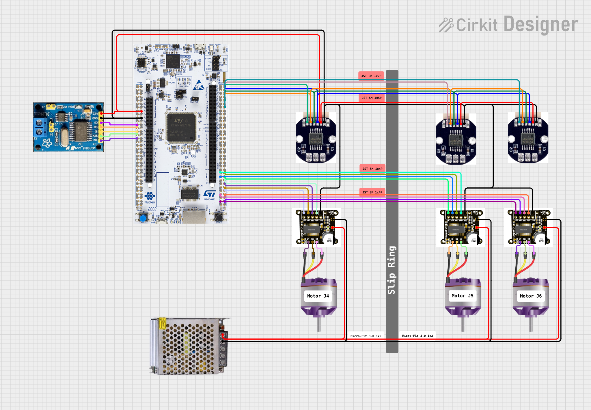
Circuit Documentation
Summary
This circuit is designed to control multiple brushless motors using SimpleFOCMini motor controllers. It includes magnetic encoder position sensors (AS5048) for feedback and a CAN BUS module for communication. The STM32H7 microcontroller serves as the central processing unit, interfacing with the encoders and motor controllers, and managing the CAN BUS communication. A 12V 5A power supply provides the necessary power for the motors and the electronic components.
Component List
SimpleFOCMini Motor Controller
- Description: A compact motor controller designed for controlling brushless motors with ease.
- Pins: IN1, IN2, IN3, EN, GND, Ua, Ub, Uc, -, +
AS5048 Magnetic Encoder Position Sensor
- Description: A high-resolution magnetic rotary position sensor for precise angle measurement.
- Pins: GND, nCS, CLK, MOSI, MISO, VDD5V, PWM
Brushless Motor
- Description: A three-phase brushless DC motor.
- Pins: L1, L2, L3
CAN BUS Module
- Description: A module for interfacing with the CAN bus, allowing for robust communication between devices.
- Pins: INT, SCK, SI, SO, CS, GND, VCC, J1, J11, H, L, VDD
STM32H7 Microcontroller
- Description: A high-performance microcontroller with advanced peripherals.
- Pins: Numerous GPIOs, power, and ground pins.
POWER SUPPLY 12V 5AMP
- Description: A power supply unit capable of delivering 12V at up to 5A.
- Pins: 220V Positive Pole (AC), 220V Negative Pole (AC), GND, GND (DC), 12V-24V Output (DC)
Wiring Details
SimpleFOCMini Motor Controller
- IN1, IN2, IN3: Connected to the STM32H7 GPIOs for motor control signals.
- EN: Connected to the STM32H7 GPIO for enabling the motor controller.
- GND: Common ground with the STM32H7, AS5048 sensors, CAN BUS module, and power supply.
- Ua, Ub, Uc: Connected to the corresponding L1, L2, L3 pins of the Brushless Motors.
- -, +: Connected to the GND (DC) and 12V-24V Output (DC) of the power supply, respectively.
AS5048 Magnetic Encoder Position Sensor
- VDD5V: Connected to the 3V3 pin of the STM32H7 and VCC of the CAN BUS module.
- GND: Common ground with other components.
- nCS, CLK, MOSI, MISO: Connected to the corresponding GPIOs on the STM32H7 for SPI communication.
- PWM: Not connected in the provided net list.
Brushless Motor
- L1, L2, L3: Connected to the Ua, Ub, Uc outputs of the corresponding SimpleFOCMini motor controllers.
CAN BUS Module
- INT, SCK, SI, SO, CS: Connected to the corresponding GPIOs on the STM32H7.
- GND: Common ground with other components.
- VCC: Connected to the 3V3 pin of the STM32H7.
STM32H7 Microcontroller
- 3V3: Provides power to the AS5048 sensors and the CAN BUS module.
- GND: Common ground with other components.
- GPIOs: Connected to various pins on the SimpleFOCMini motor controllers, AS5048 sensors, and CAN BUS module for control and communication.
POWER SUPPLY 12V 5AMP
- GND (DC): Common ground with the SimpleFOCMini motor controllers.
- 12V-24V Output (DC): Provides power to the SimpleFOCMini motor controllers.
Documented Code
sketch.ino
void setup() {
  // put your setup code here, to run once:

}

void loop() {
  // put your main code here, to run repeatedly:

}
documentation.txt
(No additional documentation provided)
This concludes the documentation for the provided circuit design. The circuit is set up for basic operation, and further implementation details would be required to fully utilize the capabilities of the components, such as motor control algorithms and CAN BUS communication protocols.