
Circuit Documentation
Summary of the Circuit
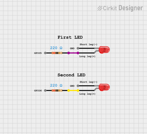
This circuit consists of two red LEDs, each connected in series with a resistor. The purpose of the resistors is to limit the current flowing through the LEDs to prevent them from being damaged by excessive current. The circuit is designed to be connected to a power source that matches the forward voltage and current requirements of the LEDs when considering the resistance value. There are no microcontrollers or programmable devices in this circuit, and hence no embedded code is associated with it.
Component List
LED: Two Pin (red)
- Description: A red light-emitting diode (LED) with two pins: an anode and a cathode.
- Purpose: To emit red light when powered.
- Properties: None specified.
Resistor
- Description: A passive two-terminal electrical component that implements electrical resistance as a circuit element.
- Purpose: To limit the current flowing through the LED.
- Properties:
- Resistance: 220 Ohms
Comment
- Description: A placeholder for comments within the circuit design.
- Purpose: Typically used to add notes or explanations within the circuit design, but no specific comments are provided here.
- Properties: None specified.
Wiring Details
LED: Two Pin (red)
- Anode: Connected to the pin2 of a Resistor.
- Cathode: To be connected to the negative side of the power supply (not specified in the net list).
Resistor
- Pin1: To be connected to the positive side of the power supply (not specified in the net list).
- Pin2: Connected to the anode of a red LED.
Documented Code
No code has been provided for this circuit as there are no microcontroller or programmable components involved.
Please note that the instance IDs have been omitted from this document as per the request. The wiring details only include connections specified in the net list, and any connections to the power supply or other components not listed would need to be inferred or provided separately.