
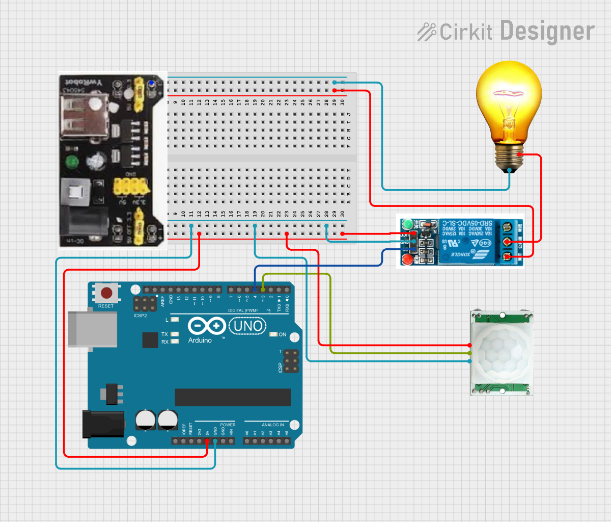
Automatic Light Control Circuit Documentation
Summary
This circuit is designed to control an AC bulb automatically using a PIR (Passive Infrared) motion sensor and a 5V relay. The system operates by detecting motion through the PIR sensor, which then triggers the relay to switch on the AC bulb. The Arduino UNO microcontroller is used to process the signal from the PIR sensor and control the relay accordingly. Additionally, the circuit keeps a count of motion detection events and outputs this information to the serial monitor.
Component List
PIR/Motion Sensor
- Description: A sensor that detects motion based on changes in infrared levels.
- Pins: GND, OUTPUT, VCC
5V Relay
- Description: An electromechanical switch that allows control of a high-power circuit by a low-power signal.
- Pins: Normally Open, Common terminal, Normally Closed, In, GND, VCC
AC Bulb
- Description: A standard AC-powered light bulb.
- Pins: P (Phase), N (Neutral)
MB102 Breadboard Power Supply Module 3.3V/5V
- Description: A power supply module that provides 3.3V and 5V outputs for breadboard projects.
- Pins: GND, 3.3V, 5V
Arduino UNO
- Description: A microcontroller board based on the ATmega328P.
- Pins: UNUSED, IOREF, Reset, 3.3V, 5V, GND, Vin, A0-A5, SCL, SDA, AREF, D0-D13
Wiring Details
PIR/Motion Sensor
- GND: Connected to Arduino UNO GND
- OUTPUT: Connected to Arduino UNO Digital Pin 3
- VCC: Connected to Arduino UNO 5V
5V Relay
- Normally Open: Not connected
- Common terminal: Connected to AC Bulb P (Phase)
- Normally Closed: Not connected
- In: Connected to Arduino UNO Digital Pin 4
- GND: Connected to Arduino UNO GND
- VCC: Connected to Arduino UNO 5V
AC Bulb
- P (Phase): Connected to 5V Relay Common terminal
- N (Neutral): Not connected
MB102 Breadboard Power Supply Module 3.3V/5V
- GND: Connected to AC Bulb N (Neutral)
- 3.3V: Not used
- 5V: Not used
Arduino UNO
- GND: Connected to PIR/Motion Sensor GND and 5V Relay GND
- 5V: Connected to PIR/Motion Sensor VCC and 5V Relay VCC
- D3: Connected to PIR/Motion Sensor OUTPUT
- D4: Connected to 5V Relay In
Documented Code
/*
 * Project: Automatic Light with PIR Sensor and Relay
 * Description: This code controls an automatic light using a PIR sensor
 * and a relay. Whenever the PIR sensor detects motion, the relay is activated
 * to turn on a bulb. Additionally, the code counts the number of times
 * a person is detected and prints it on the serial monitor.
 */

// Pin definitions
const int pirPin = 3; // PIR sensor output pin
const int relayPin = 4; // Relay input pin

// Variables
int motionDetected = 0; // Motion detection counter

void setup() {
  // Pin configuration
  pinMode(pirPin, INPUT);
  pinMode(relayPin, OUTPUT);
  // Serial monitor initialization
  Serial.begin(9600);
  // Initialize relay to off state
  digitalWrite(relayPin, LOW);
}

void loop() {
  // Read the state of the PIR sensor
  int pirState = digitalRead(pirPin);
  if (pirState == HIGH) {
    // If motion is detected
    digitalWrite(relayPin, HIGH); // Turn on the light
    motionDetected++; // Increment the counter
    Serial.print("Motion detected: ");
    Serial.println(motionDetected);
    delay(5000); // Keep the light on for 5 seconds
  } else {
    // If no motion is detected
    digitalWrite(relayPin, LOW); // Turn off the light
  }
  delay(100); // Small delay to avoid bouncing
}
This code is designed to be uploaded to the Arduino UNO microcontroller. It sets up the necessary pin modes, initializes the serial communication, and contains the main logic for controlling the relay based on the PIR sensor's output. The relay is turned on when motion is detected and turned off otherwise. The delay functions are used to manage the timing of the light and to debounce the PIR sensor signal.