
Arduino-Controlled Ultrasonic Distance Measurement with Relay-Activated Gearmotor and Buzzer Notification
View and Edit Project In Cirkit Designer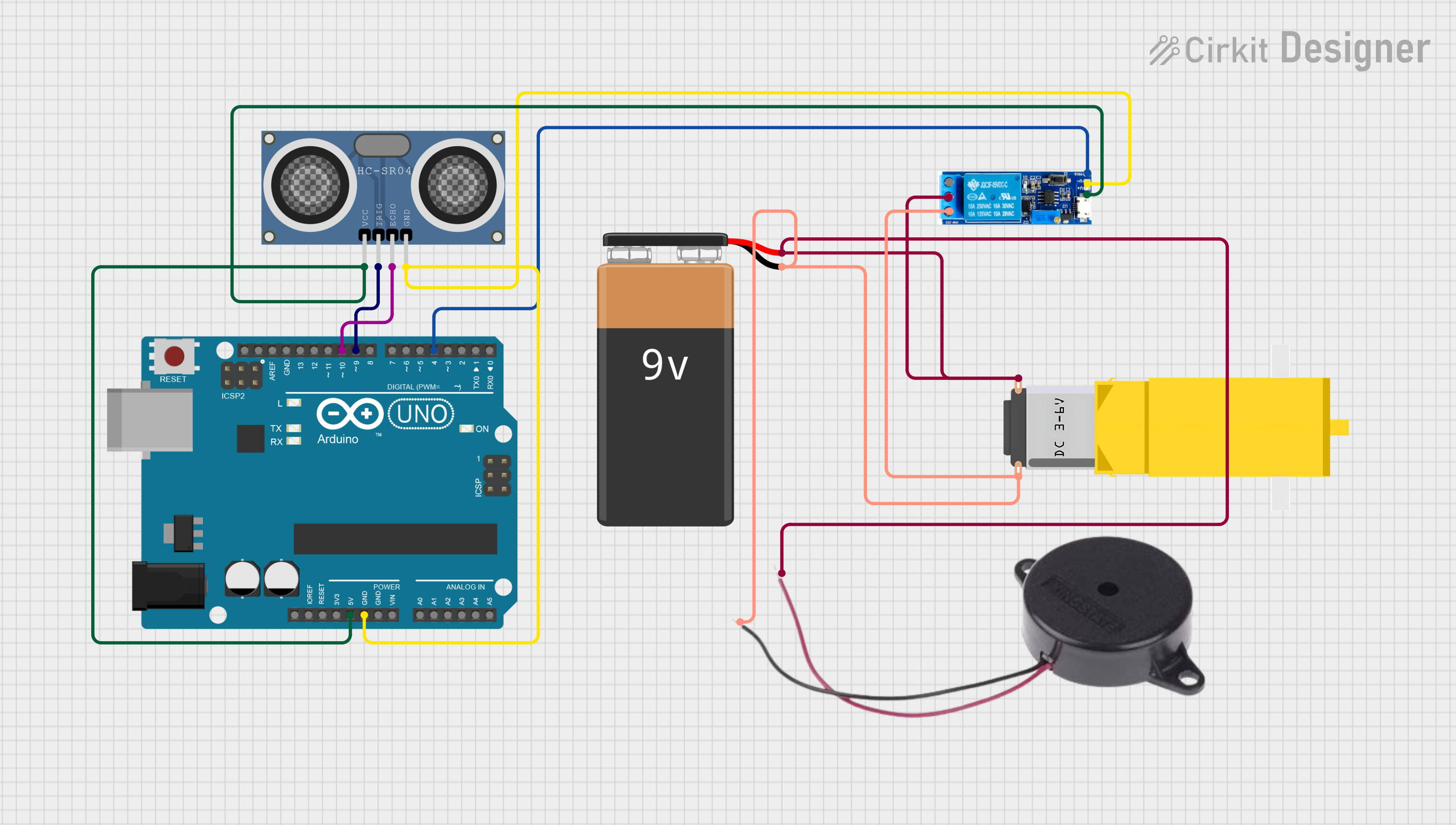
Circuit Documentation
Summary of the Circuit
This circuit is designed to interface an HC-SR04 Ultrasonic Distance Sensor with an Arduino UNO for distance measurement. The Arduino controls a relay module, which in turn can switch a gearmotor and a buzzer on and off. The gearmotor and buzzer are powered by a 9V battery. The relay module is used to control the high-power circuit of the gearmotor and buzzer, isolating it from the low-power control circuitry of the Arduino.
Component List
HC-SR04 Ultrasonic Distance Sensor (Wokwi Compatible)
- Description: A sensor that measures distance by emitting ultrasonic waves and measuring the time taken for the echo to return.
- Pins: VCC, TRIG, ECHO, GND
Arduino UNO
- Description: A microcontroller board based on the ATmega328P, widely used for building digital devices and interactive objects that can sense and control objects in the physical world.
- Pins: UNUSED, IOREF, Reset, 3.3V, 5V, GND, Vin, A0-A5, SCL, SDA, AREF, D0-D13
Relay module 5v-30v
- Description: An electrically operated switch that allows you to control a high-power circuit with a low-power signal.
- Pins: common contact, normally open, normally closed, trigger, V-, V+
Gearmotor DC / Motorreductor
- Description: A DC motor combined with a gearbox to reduce the speed and increase the torque.
- Pins: Pin1, Pin2
9V Battery
- Description: A standard 9V battery used to provide power to the circuit.
- Pins: -, +
Buzzer
- Description: An electronic buzzer that emits sound when powered.
- Pins: POSITIVE, NEGATIVE
Wiring Details
HC-SR04 Ultrasonic Distance Sensor
- VCC connected to Arduino UNO 5V
- TRIG connected to Arduino UNO D9
- ECHO connected to Arduino UNO D10
- GND connected to Arduino UNO GND
Arduino UNO
- 5V connected to HC-SR04 VCC and Relay module V+
- GND connected to HC-SR04 GND and Relay module V-
- D9 connected to HC-SR04 TRIG
- D10 connected to HC-SR04 ECHO
- D4 connected to Relay module trigger
Relay module 5v-30v
- V+ connected to Arduino UNO 5V
- V- connected to Arduino UNO GND
- trigger connected to Arduino UNO D4
- common contact connected to 9V Battery +
- normally closed connected to Gearmotor Pin2 and Buzzer NEGATIVE
Gearmotor DC / Motorreductor
- Pin1 connected to 9V Battery +
- Pin2 connected to Relay module normally closed and Buzzer NEGATIVE
9V Battery
-
- connected to Relay module common contact and Gearmotor Pin1
-
- connected to Buzzer NEGATIVE
Buzzer
- POSITIVE connected to 9V Battery +
- NEGATIVE connected to Relay module normally closed and Gearmotor Pin2
Documented Code
Arduino UNO Code (sketch.ino)
void setup() {
  // put your setup code here, to run once:

}

void loop() {
  // put your main code here, to run repeatedly:

}
Note: The provided code is a template and does not contain any functional code. It needs to be filled in with the logic for controlling the HC-SR04 sensor, the relay module, and subsequently the gearmotor and buzzer based on the sensor's readings.