
ESP32-Based Wi-Fi Controlled Servo Gate System with Pushbutton Activation
View and Edit Project In Cirkit Designer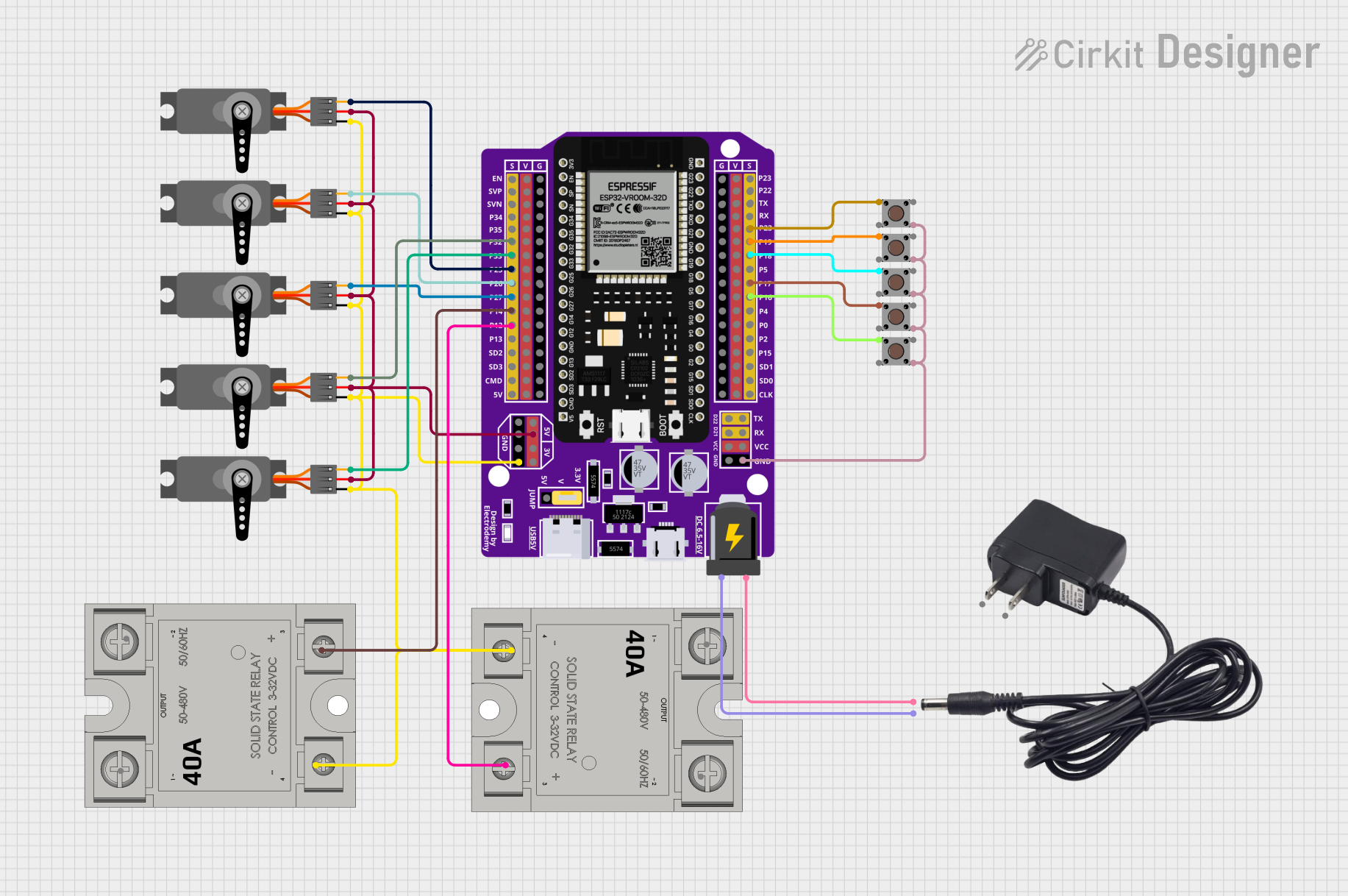
Circuit Documentation
Summary
This circuit is designed to control multiple servos and solid-state relays (SSRs) using an ESP32 microcontroller. The circuit includes five servos, five pushbuttons, two SSRs, and a 12V adapter. The ESP32 is programmed to read the state of the pushbuttons and control the servos and SSRs accordingly.
Component List
ESP32 - 38 pins Expansion Board
- Description: A microcontroller board with 38 pins, used for controlling various components in the circuit.
- Pins: EN, SVP, SVN, P34, P35, P32, P33, P25, P26, P27, P14, P12, P13, SD2, SD3, CMD, 5V, P23, P22, TX, RX, P19, P18, P5, P17, P16, P4, P0, P2, P15, SD1, SD0, CLK, VCC, G, D22, D21, 3V, V, +, -
Servo (5 units)
- Description: A servo motor used for precise control of angular position.
- Pins: GND, VCC, PWM
Pushbutton (5 units)
- Description: A simple pushbutton used for user input.
- Pins: Pin 3 (out), Pin 4 (out), Pin 1 (in), Pin 2 (in)
SSR-40A (2 units)
- Description: A solid-state relay used for switching high-power devices.
- Pins: -, +, Lin, Lout
12V Adapter
- Description: A power adapter providing 12V DC.
- Pins: VCC, GND
Wiring Details
ESP32 - 38 pins Expansion Board
- P32: Connected to Servo (PWM)
- P33: Connected to Servo (PWM)
- P25: Connected to Servo (PWM)
- P26: Connected to Servo (PWM)
- P27: Connected to Servo (PWM)
- P14: Connected to SSR-40A (+)
- P12: Connected to SSR-40A (+)
- P23: Connected to Pushbutton (Pin 3 (out))
- P19: Connected to Pushbutton (Pin 3 (out))
- P18: Connected to Pushbutton (Pin 3 (out))
- P17: Connected to Pushbutton (Pin 3 (out))
- P16: Connected to Pushbutton (Pin 3 (out))
- G: Connected to Pushbutton (Pin 2 (in)), Pushbutton (Pin 2 (in)), Pushbutton (Pin 2 (in)), Pushbutton (Pin 2 (in)), Pushbutton (Pin 2 (in)), Servo (GND), Servo (GND), SSR-40A (-), Servo (GND), Servo (GND), SSR-40A (-), Servo (GND)
- 5V: Connected to Servo (VCC), Servo (VCC), Servo (VCC), Servo (VCC), Servo (VCC)
- +: Connected to 12V Adapter (GND)
- -: Connected to 12V Adapter (VCC)
Servo
- GND: Connected to ESP32 (G)
- VCC: Connected to ESP32 (5V)
- PWM: Connected to ESP32 (P32, P33, P25, P26, P27)
Pushbutton
- Pin 3 (out): Connected to ESP32 (P23, P19, P18, P17, P16)
- Pin 2 (in): Connected to ESP32 (G)
SSR-40A
- +: Connected to ESP32 (P14, P12)
- -: Connected to ESP32 (G)
12V Adapter
- GND: Connected to ESP32 (+)
- VCC: Connected to ESP32 (-)
Code Documentation
#include <ESP32Servo.h>

#define NUM_GATES 5
#define MOTOR1_RELAY_PIN 12
#define MOTOR2_RELAY_PIN 14
#define MOTOR_DELAY 5000
#define SERVO_DELAY 10000

ESP32Servo servos[NUM_GATES];
int gatePins[NUM_GATES] = {25, 26, 27, 32, 33}; // Pins for the servos on the ESP32
int contactPins[NUM_GATES] = {16, 17, 18, 19, 23}; // Pins for the input contacts on the ESP32
bool gateStates[NUM_GATES] = {false, false, false, false, false};
int motor1State = LOW;
int motor2State = LOW;
int motorOrder = 0;

void setup() {
  for (int i = 0; i < NUM_GATES; i++) {
    servos[i].attach(gatePins[i]);
    pinMode(contactPins[i], INPUT_PULLUP);
  }
  pinMode(MOTOR1_RELAY_PIN, OUTPUT);
  pinMode(MOTOR2_RELAY_PIN, OUTPUT);
  digitalWrite(MOTOR1_RELAY_PIN, motor1State);
  digitalWrite(MOTOR2_RELAY_PIN, motor2State);
}

void loop() {
  int activeGates = 0;
  for (int i = 0; i < NUM_GATES; i++) {
    bool contactState = digitalRead(contactPins[i]) == LOW;
    if (contactState && !gateStates[i]) {
      gateStates[i] = true;
      servos[i].write(90); // Open servo
      delay(SERVO_DELAY);
    } else if (!contactState && gateStates[i]) {
      gateStates[i] = false;
      delay(SERVO_DELAY);
      servos[i].write(0); // Close servo
    }
    if (gateStates[i]) {
      activeGates++;
    }
  }

  if (activeGates > 0) {
    if (motor1State == LOW) {
      motor1State = HIGH;
      digitalWrite(MOTOR1_RELAY_PIN, motor1State);
    }
    if (activeGates > 1 && motor2State == LOW) {
      motor2State = HIGH;
      digitalWrite(MOTOR2_RELAY_PIN, motor2State);
    } else if (activeGates == 1 && motor2State == HIGH) {
      motor2State = LOW;
      digitalWrite(MOTOR2_RELAY_PIN, motor2State);
    }
  } else {
    if (motor1State == HIGH) {
      delay(MOTOR_DELAY);
      motor1State = LOW;
      digitalWrite(MOTOR1_RELAY_PIN, motor1State);
    }
    if (motor2State == HIGH) {
      motor2State = LOW;
      digitalWrite(MOTOR2_RELAY_PIN, motor2State);
    }
  }
}

void changeMotorOrder() {
  motorOrder = (motorOrder + 1) % 2;
}
This code is designed to control five servos and two SSRs using an ESP32 microcontroller. The servos are connected to specific pins on the ESP32, and their states are controlled based on the input from pushbuttons. The SSRs are used to control motors, which are activated based on the state of the servos. The code includes a setup function to initialize the pins and a loop function to continuously check the state of the pushbuttons and control the servos and SSRs accordingly.