
Circuit Documentation
Summary
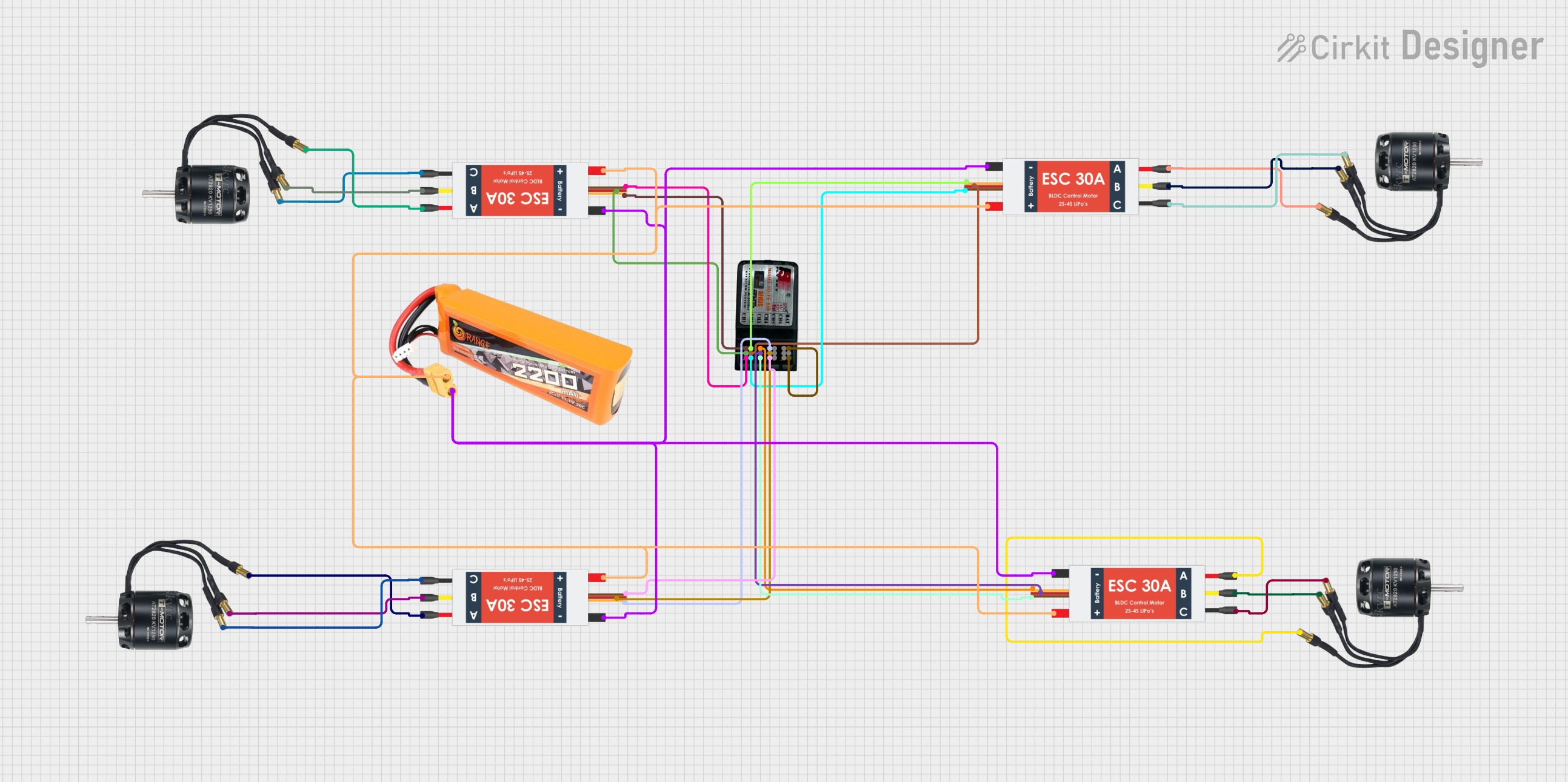
The circuit in question is designed to control four Brushless DC (BLDC) motors using four Electronic Speed Controllers (ESCs), which are in turn managed by signals from an FS-CT6B Receiver. The receiver gets its power from one of the ESCs, which also distribute power to the motors. A single lipo battery provides the power source for the entire system.
Component List
BLDC Motors
- Description: Brushless DC motors are used for high-performance applications. They are efficient, have high torque-to-weight ratios, and are capable of high speeds.
- Purpose: In this circuit, the BLDC motors are the actuators, responsible for converting electrical energy into mechanical rotation.
Electronic Speed Controllers (ESC)
- Description: ESCs are electronic circuits that control the speed and direction of a brushless motor.
- Purpose: They regulate the power supplied to the motors based on input signals from the receiver.
FS-CT6B Receiver
- Description: A radio receiver designed for remote control applications in models and drones.
- Purpose: It receives signals from a remote transmitter and outputs control signals to the ESCs.
Lipo Battery 2200mAh 30C
- Description: A rechargeable lithium polymer battery with a capacity of 2200mAh and a discharge rate of 30C.
- Purpose: It provides the power necessary to drive the ESCs and, subsequently, the BLDC motors.
Wiring Details
BLDC Motors
- Wire A: Connected to the M1 pin of its corresponding ESC.
- Wire B: Connected to the M2 pin of its corresponding ESC.
- Wire C: Connected to the M3 pin of its corresponding ESC.
Electronic Speed Controllers (ESC)
- Battery VCC: All ESCs are connected to the VCC pin of the lipo battery.
- Battery GND: All ESCs are connected to the GND pin of the lipo battery.
- Signal: Each ESC has a signal wire connected to a corresponding channel on the FS-CT6B Receiver (channels 1 to 4).
- 5v out: Each ESC provides a 5V output to the corresponding positive channel on the FS-CT6B Receiver.
- GND out: Each ESC provides a ground connection to the corresponding negative channel on the FS-CT6B Receiver.
- M1, M2, M3: Each set of these pins is connected to the three wires of a corresponding BLDC Motor.
FS-CT6B Receiver
- Bind: Connected to the -ve pin for binding purposes.
- +ve: Receives 5V from the 5v out pin of one of the ESCs.
- -ve: Connected to the GND out pin of the same ESC.
- Channels 1 to 4: Each channel is connected to the signal pin of a corresponding ESC.
- Channel +ve (1+ to 4+): Each positive channel is connected to the 5v out pin of a corresponding ESC.
- Channel -ve (1- to 4-): Each negative channel is connected to the GND out pin of a corresponding ESC.
Documented Code
There is no embedded code provided for the microcontrollers in this circuit. If code is later provided, it will be documented in this section.