
Wi-Fi Controlled Air Quality Monitor with Automated Fan and Alert System
View and Edit Project In Cirkit Designer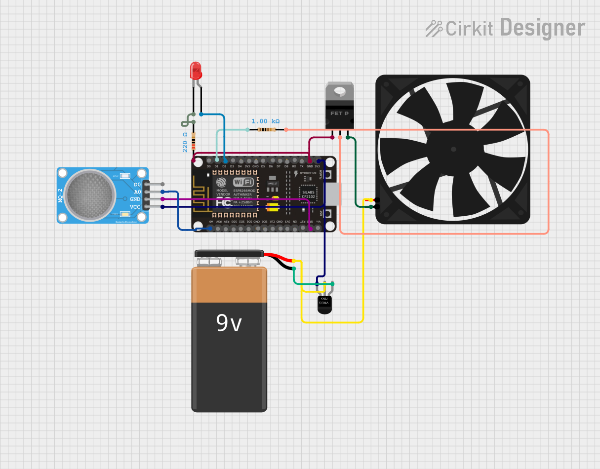
Circuit Documentation
Summary
This circuit is designed to interface an MQ-2 gas sensor with an ESP8266 NodeMCU microcontroller for gas detection purposes. The circuit includes a voltage regulator to step down the voltage from a 9V battery to a level suitable for the ESP8266 and the MQ-2 sensor. It also features a red LED indicator and a fan, which can be controlled by the microcontroller. A pMOS transistor is used to switch the fan on and off, and resistors are included for current limiting and pull-up configurations.
Component List
LED: Two Pin (red)
- Description: A red light-emitting diode used as an indicator.
- Pins: cathode, anode
9V Battery
- Description: A 9-volt battery provides power to the circuit.
- Pins: -, +
MQ-2 Sensor
- Description: A gas sensor for detecting a variety of gases including LPG, smoke, and alcohol vapor.
- Pins: VCC, GND, A0, D0
Fan
- Description: An electric fan used for ventilation or gas dispersion.
- Pins: GND, 5V
pMOS Transistor (MOSFET)
- Description: A p-channel MOSFET used as a switch to control the fan.
- Pins: gate, drain, source
Resistor (1k Ohms)
- Description: A resistor with a resistance of 1000 Ohms, used for current limiting or pull-up/down configurations.
- Pins: pin1, pin2
ESP8266 NodeMCU
- Description: A microcontroller with Wi-Fi capabilities for controlling and interfacing with various components.
- Pins: D0, D1, D2, D3, D4, 3V3, GND, D5, D6, D7, D8, RX, TX, A0, RSV, SD3, SD2, SD1, CMD, SD0, CLK, EN, RST, VIN
Resistor (220 Ohms)
- Description: A resistor with a resistance of 220 Ohms, typically used for LED current limiting.
- Pins: pin1, pin2
Voltage Regulator
- Description: A device that maintains a constant voltage level to the load.
- Pins: GND, IN, OUT
Wiring Details
LED: Two Pin (red)
- Anode: Connected to ESP8266 NodeMCU D2 pin.
- Cathode: Connected to a 220 Ohm resistor.
9V Battery
- + (Positive): Connected to the IN pin of the Voltage Regulator and the 5V pin of the Fan.
- - (Negative): Connected to the GND pin of the Voltage Regulator.
MQ-2 Sensor
- VCC: Connected to the 3V3 output of the Voltage Regulator.
- GND: Connected to the GND pin of the ESP8266 NodeMCU.
- A0: Connected to the A0 pin of the ESP8266 NodeMCU.
- D0: Not connected in this configuration.
Fan
- 5V: Connected to the + terminal of the 9V Battery.
- GND: Connected to the source pin of the pMOS Transistor.
pMOS Transistor (MOSFET)
- Gate: Connected to the GND pin of the ESP8266 NodeMCU through a 1k Ohm resistor.
- Drain: Connected to the pin2 of the 1k Ohm resistor.
- Source: Connected to the GND pin of the Fan.
Resistor (1k Ohms)
- Pin1: Connected to the D1 pin of the ESP8266 NodeMCU.
- Pin2: Connected to the drain pin of the pMOS Transistor.
ESP8266 NodeMCU
- 3V3: Connected to the OUT pin of the Voltage Regulator.
- GND: Connected to the GND pin of the MQ-2 Sensor and the gate pin of the pMOS Transistor.
- D0, D1, D2: Connected to various components for control signals.
- A0: Connected to the A0 pin of the MQ-2 Sensor.
Resistor (220 Ohms)
- Pin1: Connected to the cathode of the LED.
- Pin2: Connected to the GND pin of the ESP8266 NodeMCU.
Voltage Regulator
- GND: Connected to the - terminal of the 9V Battery.
- IN: Connected to the + terminal of the 9V Battery.
- OUT: Connected to the 3V3 pin of the ESP8266 NodeMCU and the VCC pin of the MQ-2 Sensor.
Documented Code
There is no code provided for the microcontroller in this circuit. The code would typically include initialization of the GPIO pins, reading from the MQ-2 sensor, controlling the LED and fan based on sensor readings, and possibly communicating data over Wi-Fi using the ESP8266's capabilities.