
Arduino Leonardo-Based Gaming Steering Wheel with Pedals and Gear Shifter
View and Edit Project In Cirkit Designer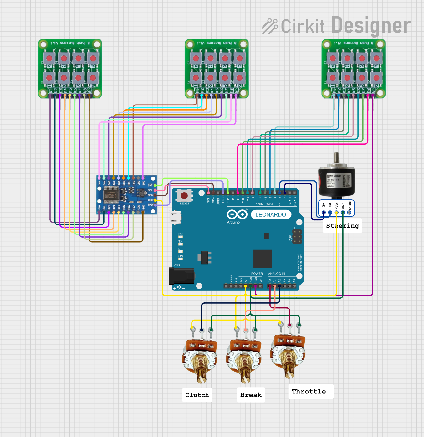
Circuit Documentation
Summary
This circuit is designed to function as a gaming steering wheel with three pedals and a gear shifter. It allows for 900-degree rotation and includes the following components:
- 600 PPR Optical Rotary Encoder (Steering Wheel)
- 3 Potentiometers (Pedals)
- 8 Push Buttons (Gear Shifter)
- IO Expander with additional push buttons
The circuit is controlled by an Arduino Leonardo (Rev3b) microcontroller, which reads inputs from the encoder, potentiometers, and push buttons, and processes these inputs to simulate a gaming steering wheel setup.
Component List
Arduino Leonardo (Rev3b)
- Description: Microcontroller board based on the ATmega32u4.
- Pins: D0/RX, D1/TX, D2/SDA, D3 PWM/SCL, D4/A6, D5 PWM, D6 PWM/A7, D7, n.c., IOREF, RESET, 3V3, 5V, GND, VIN, A0, A1, A2, A3, A4, A5, D8/A8, D9 PWM/A9, D10 PWM/A10, D11 PWM, D12/A11, D13 PWM, AREF, SDA, SCL
PR-Rotary Potentiometer
- Description: Rotary potentiometer used to measure the position of the pedals.
- Pins: GND, OUT, VCC
8 Push Button Board PCB
- Description: PCB with 8 push buttons used for the gear shifter.
- Pins: K1, K2, K3, K4, K5, K6, K7, K8, GROUND
IO Expander
- Description: Expands the number of input/output pins available.
- Pins: P07, P06, P05, P04, P03, P02, P01, P00, VDD, GND, P10, P11, P12, P13, P14, P15, P16, P17, VCC, SDA, SCL, INT
600 PPR Optical Rotary Encoder
- Description: Optical rotary encoder used to measure the rotation of the steering wheel.
- Pins: Phase A, Phase B, Vcc, GND, Shield
Wiring Details
Arduino Leonardo (Rev3b)
- D2/SDA: Connected to Phase A of the 600 PPR Optical Rotary Encoder
- D3 PWM/SCL: Connected to Phase B of the 600 PPR Optical Rotary Encoder
- D4/A6: Connected to K1 of the 8 Push Button Board PCB
- D5 PWM: Connected to K2 of the 8 Push Button Board PCB
- D6 PWM/A7: Connected to K3 of the 8 Push Button Board PCB
- D7: Connected to K4 of the 8 Push Button Board PCB
- 5V: Connected to Vcc of the 600 PPR Optical Rotary Encoder, VCC of all PR-Rotary Potentiometers, and VCC of the IO Expander
- GND: Connected to GND of the 600 PPR Optical Rotary Encoder, GND of all PR-Rotary Potentiometers, GROUND of the 8 Push Button Board PCB, and GND of the IO Expander
- A0: Connected to OUT of the first PR-Rotary Potentiometer
- A1: Connected to OUT of the second PR-Rotary Potentiometer
- A2: Connected to OUT of the third PR-Rotary Potentiometer
- D8/A8: Connected to K5 of the 8 Push Button Board PCB
- D9 PWM/A9: Connected to K6 of the 8 Push Button Board PCB
- D10 PWM/A10: Connected to K7 of the 8 Push Button Board PCB
- D11 PWM: Connected to K8 of the 8 Push Button Board PCB
- D13 PWM: Connected to INT of the IO Expander
- SDA: Connected to SDA of the IO Expander
- SCL: Connected to SCL of the IO Expander
PR-Rotary Potentiometer
- GND: Connected to GND of the Arduino Leonardo
- OUT: Connected to A0, A1, and A2 of the Arduino Leonardo (one for each potentiometer)
- VCC: Connected to 5V of the Arduino Leonardo
8 Push Button Board PCB
- K1: Connected to D4/A6 of the Arduino Leonardo
- K2: Connected to D5 PWM of the Arduino Leonardo
- K3: Connected to D6 PWM/A7 of the Arduino Leonardo
- K4: Connected to D7 of the Arduino Leonardo
- K5: Connected to D8/A8 of the Arduino Leonardo
- K6: Connected to D9 PWM/A9 of the Arduino Leonardo
- K7: Connected to D10 PWM/A10 of the Arduino Leonardo
- K8: Connected to D11 PWM of the Arduino Leonardo
- GROUND: Connected to GND of the Arduino Leonardo
IO Expander
- P00 to P07: Connected to K1 to K8 of the second 8 Push Button Board PCB
- P10 to P17: Connected to K1 to K8 of the third 8 Push Button Board PCB
- VCC: Connected to 5V of the Arduino Leonardo
- GND: Connected to GND of the Arduino Leonardo
- SDA: Connected to SDA of the Arduino Leonardo
- SCL: Connected to SCL of the Arduino Leonardo
- INT: Connected to D13 PWM of the Arduino Leonardo
600 PPR Optical Rotary Encoder
- Phase A: Connected to D2/SDA of the Arduino Leonardo
- Phase B: Connected to D3 PWM/SCL of the Arduino Leonardo
- Vcc: Connected to 5V of the Arduino Leonardo
- GND: Connected to GND of the Arduino Leonardo
Code Documentation
#include <Wire.h>
#include <Adafruit_MCP23017.h>
#include <Bounce2.h>

/*
 * Gaming Steering Wheel with 3 Pedals and Gear Shifter
 * Allows 900-degree rotation
 * Components:
 * - 600 PPR Optical Rotary Encoder (Steering Wheel)
 * - 3 Potentiometers (Pedals)
 * - 8 Push Buttons (Gear Shifter)
 * - IO Expander with additional push buttons
 */

// Pin definitions for Arduino
const int encoderPinA = 2; // D2/SDA
const int encoderPinB = 3; // D3 PWM/SCL
const int pedal1Pin = A0;  // A0
const int pedal2Pin = A1;  // A1
const int pedal3Pin = A2;  // A2
const int buttonPins[] = {4, 5, 6, 7, 8, 9, 10, 11}; // D4 to D11
const int ledPin = 13; // Built-in LED for error indication

// IO Expander
Adafruit_MCP23017 mcp;
const int ioExpanderButtonPins[] = {0, 1, 2, 3, 4, 5, 6, 7, 10, 11, 12, 13, 14, 15, 16, 17}; // P00 to P07 and P10 to P17

// Variables for encoder
volatile int lastEncoded = 0;
volatile long encoderValue = 0;
volatile bool encoderUpdated = false; // Flag to indicate encoder update

// Debouncing variables
const int debounceDelay = 50; // 50 ms debounce delay
Bounce buttonDebouncers[8];
bool buttonStates[8] = {HIGH, HIGH, HIGH, HIGH, HIGH, HIGH, HIGH, HIGH}; // Initialize button states
bool ioExpanderButtonStates[16] = {HIGH, HIGH, HIGH, HIGH, HIGH, HIGH, HIGH, HIGH, HIGH, HIGH, HIGH, HIGH, HIGH, HIGH, HIGH, HIGH}; // Initialize IO expander button states

// Non-blocking delay variables
unsigned long previousMillis = 0;
const long interval = 100;

// Global variables for pedal values
int pedal1Value, pedal2Value, pedal3Value;

void setup() {
  Serial.begin(115200); // Increased baud rate for faster communication

  // Initialize encoder pins
  pinMode(encoderPinA, INPUT);
  pinMode(encoderPinB, INPUT);
  attachInterrupt(digitalPinToInterrupt(encoderPinA), updateEncoder, CHANGE); // D2 on Leonardo
  attachInterrupt(digitalPinToInterrupt(encoderPinB), updateEncoder, CHANGE); // D3 on Leonardo

  // Initialize pedal pins
  pinMode(pedal1Pin, INPUT);
  pinMode(pedal2Pin, INPUT);
  pinMode(pedal3Pin, INPUT);

  // Initialize button pins with debouncers
  for (int i = 0; i < 8; i++) {
    pinMode(buttonPins[i], INPUT_PULLUP);
    buttonDebouncers[i].attach(buttonPins[i]);
    buttonDebouncers[i].interval(debounceDelay