
Arduino and ESP8266 Wi-Fi Controlled Smart Street Light with Motion Detection and LDR
View and Edit Project In Cirkit Designer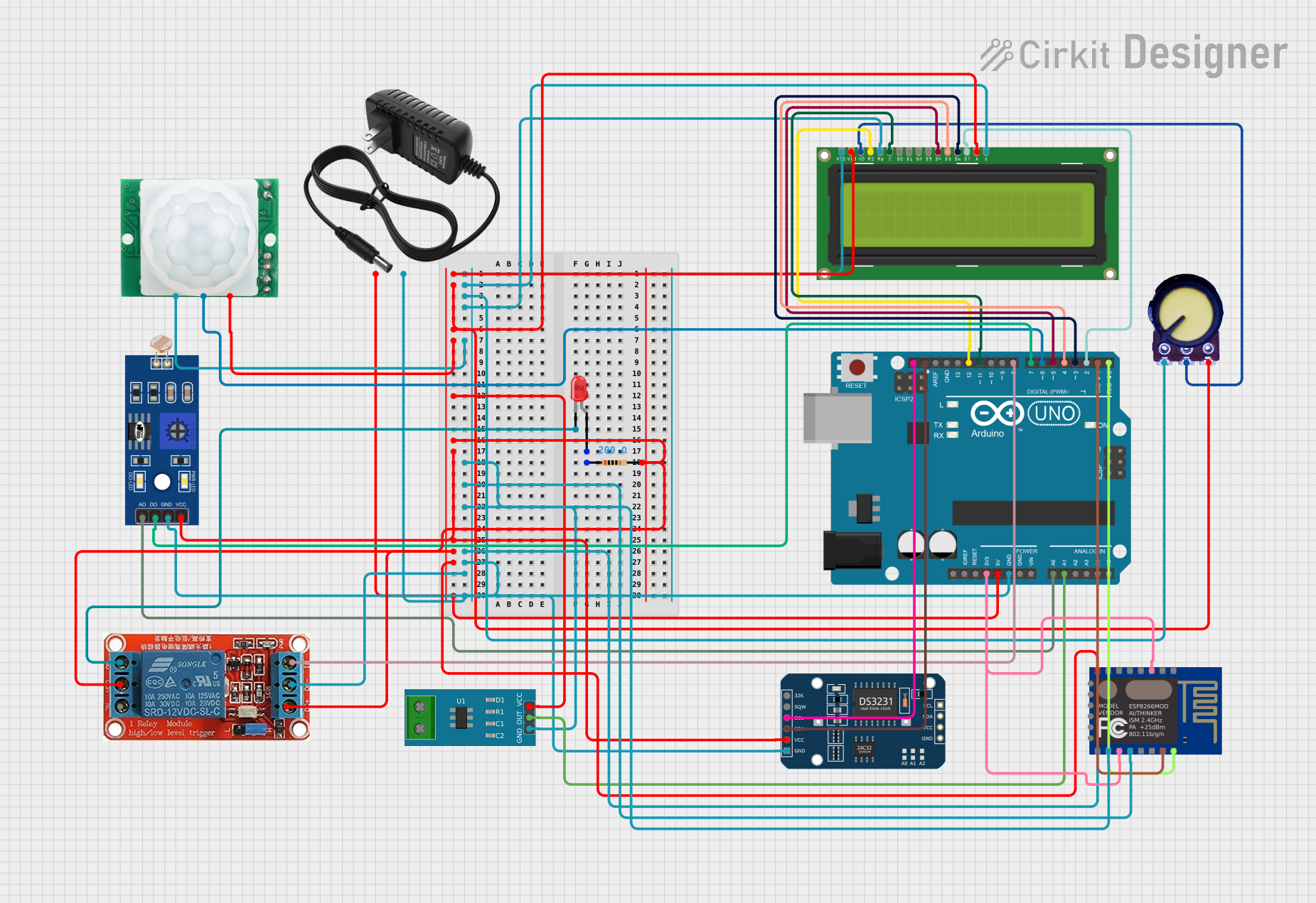
Smart Street Light Circuit Documentation
Summary
The Smart Street Light circuit is designed to control a street light automatically based on the time of day and ambient light conditions. The system uses an Arduino UNO as the main controller, interfaced with a DS3231 Real-Time Clock (RTC) for timekeeping, an LDR (Light Dependent Resistor) for ambient light sensing, an HC-SR501 Motion Sensor for detecting movement, a 12V Relay to control the light, an ESP8266 ESP-12E WiFi Module for network connectivity, and a Current Sensor to monitor the electrical current for fault detection. The circuit also includes a 16x2 LCD Display for user interface, a potentiometer for adjusting the display contrast, and an LED as an indicator. The system operates the street light at full brightness from 7 PM to 11 PM, at 50% brightness from 11 PM to 5 AM, and returns to full brightness if motion is detected during the reduced brightness period. Notifications are sent out if a fault is detected.
Component List
Arduino UNO
- Microcontroller board based on the ATmega328P
- Used as the main controller for the circuit
DS3231 RTC
- Real-Time Clock module
- Provides accurate timekeeping for the system
LDR
- Light Dependent Resistor
- Senses ambient light levels to control the street light
HC-SR501 Motion Sensor
- Passive Infrared Sensor
- Detects motion to adjust the light brightness
12V Relay
- Electromechanical switch
- Controls the on/off state of the street light
LCD Display 16x2
- Alphanumeric Liquid Crystal Display
- Displays system status and information
ESP8266 ESP-12E WiFi Module
- WiFi module for network connectivity
- Enables remote monitoring and control
Current Sensor 5A
- Monitors electrical current
- Used for fault detection in the system
12V Power Supply
- Provides power to the circuit
Potentiometer
- Variable resistor
- Adjusts the contrast of the LCD display
LED (Red)
- Indicator light
- Provides visual status of the system
Resistor (200 Ohms)
- Limits current to the LED
Wiring Details
Arduino UNO
5VandGNDto power the board and connected componentsA0connected to LDRA1connected to Current SensorSCLandSDAconnected to DS3231 RTC- Digital pins
D0toD13interfaced with various components for control and data
DS3231 RTC
SCLandSDAfor I2C communication with Arduino UNOVCCandGNDfor power
LDR
A0for analog light level output to Arduino UNOVCCandGNDfor power
HC-SR501 Motion Sensor
OUTto Arduino UNO for motion detection signalVCCandGNDfor power
12V Relay
INcontrolled by Arduino UNO to switch the relayNOandCOMused to control the street lightDC+andDC-for relay coil power
LCD Display 16x2
DB4toDB7for data interface with Arduino UNORS,E,VDD,VSSfor control and powerLEDAandLEDKfor backlightVOconnected to Potentiometer for contrast adjustment
ESP8266 ESP-12E WiFi Module
RXDandTXDfor serial communication with Arduino UNOCH_PDandGPIO_2connected to3.3Vfor enabling the moduleVCCandGNDfor power
Current Sensor 5A
OUTfor analog current output to Arduino UNOVCCandGNDfor power
Potentiometer
OutputtoVOof LCD Display for contrastVCCandGNDfor power
LED (Red)
Anodeconnected toNOof the RelayCathodeconnected through a 200 Ohm resistor toCOMof the Relay
Resistor (200 Ohms)
- Connected in series with the LED to limit current
Documented Code
/*
 * Smart Street Light with Arduino
 * This code controls a street light to automatically turn on at 7 PM or when
 * it is dark. The light operates at 100% brightness until 11 PM, then reduces
 * to 50% brightness until 5 AM. If motion is detected between 11 PM and 5 AM,
 * the light returns to 100% brightness. Notifications are sent if a fault is
 * detected, and the light can be controlled via a mobile app.
 */

#include <Wire.h>
#include <RTClib.h>
#include <ESP8266WiFi.h>
#include <ESP8266HTTPClient.h>

#define LIGHT_PIN 8
#define MOTION_PIN 6
#define LDR_PIN A0
#define CURRENT_SENSOR_PIN A1

RTC_DS3231 rtc;

const char* ssid = "your_SSID";
const char* password = "your_PASSWORD";
const char* serverName = "http://your_server.com/notify";

void setup() {
  pinMode(LIGHT_PIN, OUTPUT);
  pinMode(MOTION_PIN, INPUT);
  pinMode(LDR_PIN, INPUT);
  pinMode(CURRENT_SENSOR_PIN, INPUT);
  Serial.begin(9600);
  Wire.begin();
  rtc.begin();
  WiFi.begin(ssid, password);
  while (WiFi.status() != WL_CONNECTED) {
    delay(1000);
    Serial.println("Connecting to WiFi...");
  }
  Serial.println("Connected to WiFi");
}

void loop() {
  DateTime now = rtc.now();
  int ldrValue = analogRead(LDR_PIN);
  int motionDetected = digitalRead(MOTION_PIN);
  int currentSensorValue = analogRead(CURRENT_SENSOR_PIN);

  if (now.hour() >= 19 || ldrValue < 500) {
    if (now.hour() >= 23 && now.hour() < 5) {
      if (motionDetected) {
        analogWrite(LIGHT_PIN, 255); // 100% brightness
      } else {
        analogWrite(LIGHT_PIN, 128); // 50% brightness
      }
    } else {
      analogWrite(LIGHT_PIN, 255); // 100% brightness
    }
  } else {
    analogWrite(LIGHT_PIN, 0); // Light off
  }

  if (currentSensorValue < 100) { // Fault detected
    sendNotification();
  }

  delay(1000);
}

void sendNotification() {
  if (WiFi.status() == WL_CONNECTED) {
    HTTPClient http;
    http.begin(serverName);
    http.addHeader("Content-Type", "application/x-www-form-urlencoded");
    int httpResponseCode = http.POST("fault=detected");
    if (httpResponseCode > 0) {
      String response = http.getString();
      Serial.println(httpResponseCode);
      Serial.println(response);
    } else {
      Serial.print("Error on sending POST: ");
      Serial.println(httpResponseCode);
    }
    http.end();
  } else {
    Serial.println("WiFi Disconnected");
  }
}
This code is responsible for the logic that controls the street light based on the time and ambient conditions, as well as for sending notifications in case of a fault. It uses the Arduino UNO's built-in PWM capability to control the brightness of the light and the ESP8266 module for WiFi connectivity.