
ESP8266 NodeMCU Controlled Weighing Scale with Bluetooth Connectivity
View and Edit Project In Cirkit Designer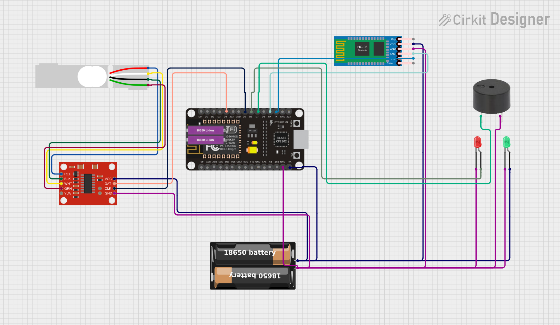
Circuit Documentation
Summary
This circuit integrates various components to form a system capable of measuring weight using a load cell, processing the data with an ESP8266 NodeMCU microcontroller, and communicating the results wirelessly via a Bluetooth module. The system also includes visual indicators (LEDs) and an audio indicator (buzzer) for user interaction. Power is supplied by a battery case connected to the circuit.
Component List
ESP8266 NodeMCU
- Microcontroller with WiFi capability.
- Provides GPIO pins for interfacing with other components.
- Can be programmed to handle sensor data and communicate wirelessly.
My Battery Case
- Power supply unit for the circuit.
- Holds batteries to provide a voltage source for the components.
18650 Li-ion Battery x 2
- Two rechargeable lithium-ion batteries.
- Provide power to the circuit when placed in the battery case.
Load Cell - Red/white/black/green
- A weight sensor that generates an electrical signal proportional to the force applied.
- Typically used in scales and weighing systems.
SparkFun Load Cell Amplifier - HX711
- An amplifier specifically designed to convert load cell signals into a digital form that microcontrollers can read.
- Interfaces between the load cell and the ESP8266 NodeMCU.
HC-05 Bluetooth Module
- A wireless communication module that enables Bluetooth connectivity.
- Allows the microcontroller to communicate with other Bluetooth-enabled devices.
LED: Two Pin (green)
- A green light-emitting diode used as a visual indicator.
- Lights up when powered.
LED: Two Pin (red)
- A red light-emitting diode used as a visual indicator.
- Lights up when powered.
Buzzer
- An audio signaling device.
- Emits a sound when powered, used for alerts or notifications.
Wiring Details
ESP8266 NodeMCU
D4connected toDATpin of the HX711 Load Cell Amplifier.D5connected toCLKpin of the HX711 Load Cell Amplifier.D6connected to the anode of the red LED.D7connected to the PIN of the buzzer.RXconnected toTXDpin of the HC-05 Bluetooth Module.TXconnected toRXDpin of the HC-05 Bluetooth Module.GNDconnected to the common ground net.VINconnected to the positive voltage net.
My Battery Case
+connected to the positive voltage net.-connected to the common ground net.
Load Cell - Red/white/black/green
E+connected toREDpin of the HX711 Load Cell Amplifier.A-connected toWHTpin of the HX711 Load Cell Amplifier.E-connected toBLKpin of the HX711 Load Cell Amplifier.A+connected toGRNpin of the HX711 Load Cell Amplifier.
SparkFun Load Cell Amplifier - HX711
DATconnected toD4of the ESP8266 NodeMCU.CLKconnected toD5of the ESP8266 NodeMCU.GNDconnected to the common ground net.VCCconnected to the positive voltage net.RED,WHT,BLK,GRNconnected to corresponding pins of the Load Cell.
HC-05 Bluetooth Module
TXDconnected toRXof the ESP8266 NodeMCU.RXDconnected toTXof the ESP8266 NodeMCU.GNDconnected to the common ground net.VCCconnected to the positive voltage net.
LED: Two Pin (green)
cathodeconnected to the common ground net.anodeconnected to the positive voltage net.
LED: Two Pin (red)
cathodeconnected to the common ground net.anodeconnected toD6of the ESP8266 NodeMCU.
Buzzer
PINconnected toD7of the ESP8266 NodeMCU.GNDconnected to the common ground net.
Documented Code
Since no code was provided in the input, this section is not applicable. However, the ESP8266 NodeMCU would typically be programmed to read data from the HX711 Load Cell Amplifier, process the weight measurement, and send the data to a paired Bluetooth device using the HC-05 module. Additionally, the NodeMCU could control the LEDs and buzzer based on certain conditions, such as weight thresholds or communication status.