Cirkit Designer
Your all-in-one circuit design IDE
Home /
Project Documentation
Wi-Fi Controlled NeoPixel Ring with ESP-8266 and Battery Power
Circuit Documentation
Summary
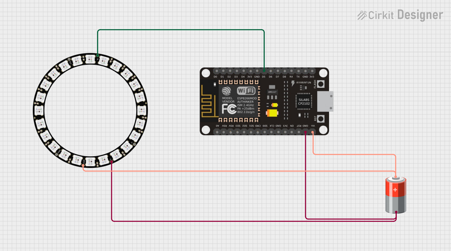
This circuit consists of an ESP-8266 microcontroller, a 5V battery, and an Adafruit 24 NeoPixel Ring. The ESP-8266 controls the NeoPixel Ring, and the entire circuit is powered by the 5V battery. The microcontroller is programmed to control a motor and an LED based on the state of a switch.
Component List
ESP-8266 Controller
- Description: A Wi-Fi enabled microcontroller used for various IoT applications.
- Pins: A0, RSV, SD3, SD5, SD1, CMD, D0, D1, D2, D3, D4, 3V3, GND, D5, D6, SD0, CLK, RST, EN, D7, D8, RX, TX, Vin, 5V
5V Battery
- Description: A power source providing 5V to the circuit.
- Pins: +, -
Adafruit 24 NeoPixel Ring
- Description: A ring of 24 individually addressable RGB LEDs.
- Pins: VDD, OUT, IN, GND
Wiring Details
ESP-8266 Controller
- D5 is connected to IN of the Adafruit 24 NeoPixel Ring.
- GND is connected to - of the 5V Battery and GND of the Adafruit 24 NeoPixel Ring.
- Vin is connected to + of the 5V Battery and VDD of the Adafruit 24 NeoPixel Ring.
5V Battery
- - is connected to GND of the ESP-8266 Controller and GND of the Adafruit 24 NeoPixel Ring.
- + is connected to Vin of the ESP-8266 Controller and VDD of the Adafruit 24 NeoPixel Ring.
Adafruit 24 NeoPixel Ring
- IN is connected to D5 of the ESP-8266 Controller.
- GND is connected to - of the 5V Battery and GND of the ESP-8266 Controller.
- VDD is connected to + of the 5V Battery and Vin of the ESP-8266 Controller.
Code Documentation
Code for ESP-8266 Controller
// Motor control pins
#define IN_A 4    // GPIO4 (D2)
#define IN_B 5    // GPIO5 (D1)

// Switch pin
#define SWITCH_PIN 14  // GPIO14 (D5)

// LED pin
#define LED_PIN 2  // GPIO2 (D4)

// Motor state
bool motorRunning = false;

void setup() {
  // Motor pins setup
  pinMode(IN_A, OUTPUT);
  pinMode(IN_B, OUTPUT);

  // Switch pin setup
  pinMode(SWITCH_PIN, INPUT_PULLUP); // Use internal pull-up resistor

  // LED pin setup
  pinMode(LED_PIN, OUTPUT);

  // Start with motor and LED off
  digitalWrite(IN_A, LOW);
  digitalWrite(IN_B, LOW);
  digitalWrite(LED_PIN, LOW);

  Serial.begin(9600);
  Serial.println("Setup Complete. Press the switch to toggle the motor.");
}

void loop() {
  // Check if the switch is pressed
  if (digitalRead(SWITCH_PIN) == LOW) {
    // Debounce delay
    delay(50);
    if (digitalRead(SWITCH_PIN) == LOW) {
      // Toggle motor state
      motorRunning = !motorRunning;
      if (motorRunning) {
        startMotor();
      } else {
        stopMotor();
      }

      // Wait for the switch to be released
      while (digitalRead(SWITCH_PIN) == LOW);
    }
  }
}

void startMotor() {
  Serial.println("Motor started.");
  analogWrite(IN_A, 255); // Full speed forward
  digitalWrite(IN_B, LOW);
  digitalWrite(LED_PIN, HIGH); // Turn on LED
}

void stopMotor() {
  Serial.println("Motor stopped.");
  digitalWrite(IN_A, LOW);
  digitalWrite(IN_B, LOW);
  digitalWrite(LED_PIN, LOW); // Turn off LED
}
This code sets up the ESP-8266 to control a motor and an LED based on the state of a switch. The motor and LED are toggled on and off when the switch is pressed. The code includes debouncing logic to ensure reliable switch operation.