
Arduino UNO Interactive Control Panel with LCD and Feedback Indicators
View and Edit Project In Cirkit Designer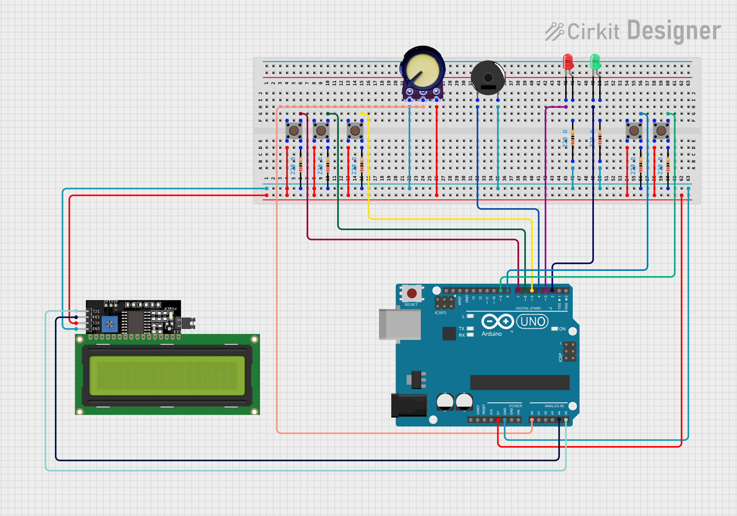
Circuit Documentation
Summary
This circuit is designed around an Arduino UNO microcontroller and includes a variety of components such as an LCD Display, LEDs, pushbuttons, a piezo buzzer, a potentiometer, and resistors. The circuit is likely intended for user interaction through the pushbuttons, visual feedback via the LEDs and LCD display, and audible alerts or feedback through the piezo buzzer. The potentiometer may be used for adjusting a parameter such as brightness or volume. The resistors are used to limit current through the LEDs and to provide pull-down functionality for the pushbuttons.
Component List
Microcontroller
- Arduino UNO: A microcontroller board based on the ATmega328P. It has 14 digital input/output pins, 6 analog inputs, a USB connection, a power jack, an ICSP header, and a reset button.
Displays
- LCD Display 16x4 I2C: A 16x4 character LCD display that uses the I2C protocol for communication.
Indicators
- LED: Two Pin (red): A red light-emitting diode used as an indicator.
- LED: Two Pin (green): A green light-emitting diode used as an indicator.
Input Devices
- Pushbutton: A momentary pushbutton switch used for user input.
Sound Devices
- Piezo Buzzer: An electronic device that emits a tone when voltage is applied.
Passive Components
- Potentiometer: A three-terminal resistor with a sliding or rotating contact that forms an adjustable voltage divider.
- Resistor: A passive two-terminal electrical component that implements electrical resistance as a circuit element.
Wiring Details
Arduino UNO
- 5V and GND pins are used to power the circuit.
- Digital Pins (D2-D9) are connected to LEDs and pushbuttons for input/output control.
- Analog Pin (A0) is connected to the potentiometer for analog input.
- I2C Pins (A4-SDA, A5-SCL) are connected to the LCD Display for communication.
LCD Display 16x4 I2C
- SCL and SDA pins are connected to the Arduino UNO for I2C communication.
- VCC and GND pins are connected to the power supply lines.
LEDs (Red and Green)
- Cathode pins are connected to the Arduino UNO digital pins with current-limiting resistors in series.
- Anode pins are connected to the positive side of the power supply through resistors.
Pushbuttons
- One side of each pushbutton is connected to the Arduino UNO digital pins.
- The other side of each pushbutton is connected to ground through a pull-down resistor.
Piezo Buzzer
- One pin is connected to the Arduino UNO digital pin for control.
- The other pin is connected to the ground.
Potentiometer
- VCC and GND pins are connected to the power supply lines.
- Output pin is connected to the Arduino UNO analog input pin.
Resistors
- Connected in series with LEDs and pushbuttons to limit current and provide pull-down functionality.
Documented Code
Arduino UNO Code (sketch.ino)
void setup() {
  // put your setup code here, to run once:

}

void loop() {
  // put your main code here, to run repeatedly:

}
Additional Notes
- The provided code is a template and does not contain any functional code. It needs to be populated with the logic to control the components based on the circuit design.
- The
setup()function is used to initialize variables, pin modes, start using libraries, etc. The code in thesetup()function will only run once, after each powerup or reset of the Arduino board. - The
loop()function is used for the main program logic. It runs continuously over and over again.
Documentation File (documentation.txt)
- No additional documentation was provided in the text file.