
Battery-Powered Emergency Alert System with NUCLEO-F072RB, SIM800L, and GPS NEO 6M
View and Edit Project In Cirkit Designer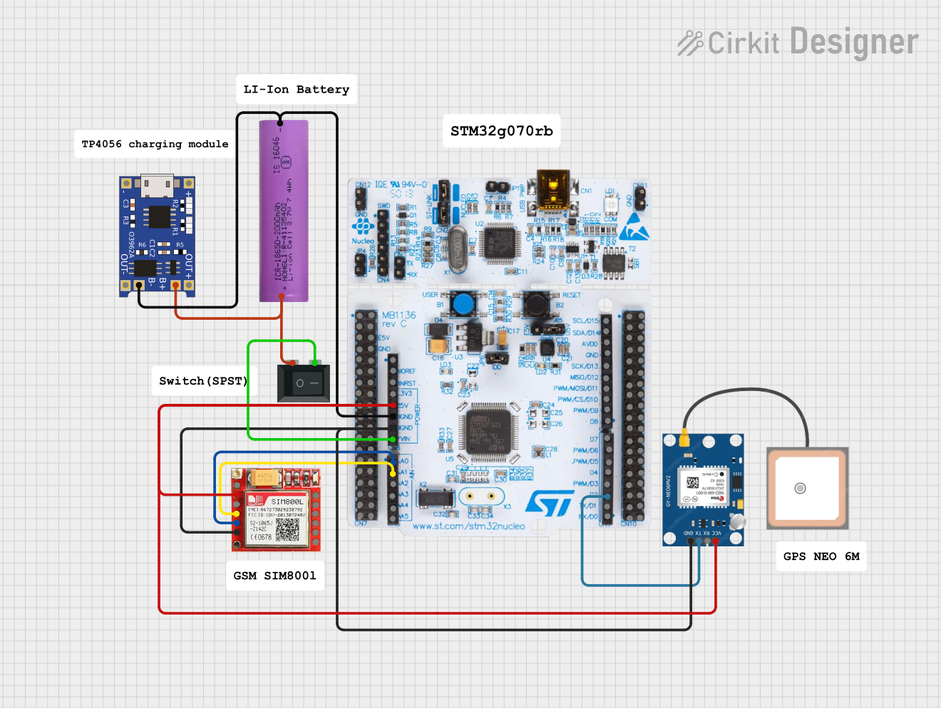
Emergency Alert System Documentation
Summary
This project is an Emergency Alert System that uses a NUCLEO-F072RB microcontroller to send alert messages and make calls to trusted persons. The system incorporates a SIM800L module for GSM communication and a GPS NEO 6M module to obtain location data. The system is powered by a Li-ion battery and includes a TP4056 module for battery management and charging. A rocker switch is used to control the power supply to the system.
Component List
TP4056
- Description: Battery management and charging module.
- Pins: OUT-, B-, B+, OUT+, IN-, IN+
Rocker Switch (SPST)
- Description: Single Pole Single Throw switch to control power.
- Pins: 1, 2
Li-ion battery 18650-2000mAh 3.7V 7.4WH
- Description: Power source for the circuit.
- Pins: +, -
SIM800L
- Description: GSM module for communication.
- Pins: NET, VCC, RST, RXD, TXD, GND, RING, DTR, MIC+, MIC-, SPK+, SPK-
GPS NEO 6M
- Description: GPS module for location tracking.
- Pins: VCC, RX, TX, GND
NUCLEO-F072RB
- Description: Microcontroller for controlling the system.
- Pins: A5, A4, A3, A2, A1, A0, VN, GND, 5V, 3V3, RESET, IOREF, SCL/D15, SDA/D14, AVDD, SCK/D13, MISO/D12, PWM/MOSI/D11, PWM/CS/D10, PWM/D9, D8, D7, PWM/D6, PWM/D5, D4, PWM/D3, D2, TX/D1, RX/D0
Wiring Details
TP4056
- B- connected to Li-ion battery (-)
- B+ connected to Li-ion battery (+)
- OUT- not connected
- OUT+ not connected
- IN- not connected
- IN+ not connected
Rocker Switch (SPST)
- Pin 1 connected to Li-ion battery (+)
- Pin 2 connected to NUCLEO-F072RB (VN)
Li-ion battery 18650-2000mAh 3.7V 7.4WH
- + connected to TP4056 (B+), Rocker Switch (Pin 1)
- - connected to TP4056 (B-), NUCLEO-F072RB (GND)
SIM800L
- VCC connected to NUCLEO-F072RB (5V)
- RXD connected to NUCLEO-F072RB (A1)
- TXD connected to NUCLEO-F072RB (A0)
- GND connected to NUCLEO-F072RB (GND), GPS NEO 6M (GND)
GPS NEO 6M
- VCC connected to NUCLEO-F072RB (5V)
- TX connected to NUCLEO-F072RB (D2)
- GND connected to SIM800L (GND), NUCLEO-F072RB (GND)
NUCLEO-F072RB
- VN connected to Rocker Switch (Pin 2)
- GND connected to Li-ion battery (-), SIM800L (GND), GPS NEO 6M (GND)
- 5V connected to SIM800L (VCC), GPS NEO 6M (VCC)
- A1 connected to SIM800L (RXD)
- A0 connected to SIM800L (TXD)
- D2 connected to GPS NEO 6M (TX)
Code Documentation
/*
 * Project: Emergency Alert System
 * Description: This project uses a NUCLEO-F072RB microcontroller to send alert messages
 * and make calls to trusted persons. It uses a SIM800L module for GSM communication
 * and a GPS NEO 6M module to get the location.
 */

#include <SoftwareSerial.h>

// Define pins for SIM800L
#define SIM800_TX A0
#define SIM800_RX A1

// Define pins for GPS NEO 6M
#define GPS_TX D2

// Create software serial ports
SoftwareSerial sim800(SIM800_TX, SIM800_RX);
SoftwareSerial gps(GPS_TX, -1); // GPS RX pin not used

void setup() {
  // Initialize serial communication
  Serial.begin(9600);
  sim800.begin(9600);
  gps.begin(9600);

  // Wait for SIM800L to initialize
  delay(1000);

  // Send SMS alert
  sendSMS("+1234567890", "Emergency! Check location.");

  // Make a call
  makeCall("+1234567890");
}

void loop() {
  // Continuously check GPS data
  if (gps.available()) {
    String gpsData = gps.readStringUntil('\n');
    Serial.println(gpsData);
  }
}

void sendSMS(const char* number, const char* message) {
  sim800.println("AT+CMGF=1"); // Set SMS mode to text
  delay(1000);
  sim800.print("AT+CMGS=\"");
  sim800.print(number);
  sim800.println("\"");
  delay(1000);
  sim800.println(message);
  delay(1000);
  sim800.write(26); // ASCII code for CTRL+Z
  delay(1000);
}

void makeCall(const char* number) {
  sim800.print("ATD");
  sim800.print(number);
  sim800.println(";");
  delay(10000); // Wait for 10 seconds
  sim800.println("ATH"); // Hang up the call
  delay(1000);
}
This documentation provides a comprehensive overview of the Emergency Alert System, including a summary, detailed component list, wiring details, and the embedded code used in the project.