
ESP8266-Based GPS and RFID Tracking System with SIM800L and Wi-Fi Connectivity
View and Edit Project In Cirkit Designer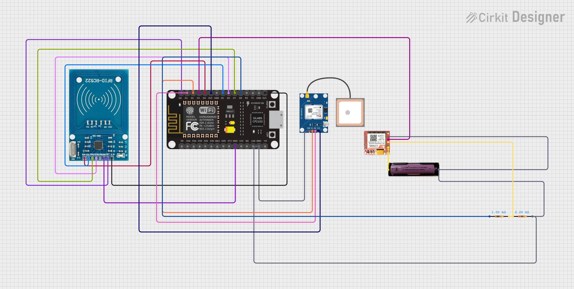
Circuit Documentation
Summary
This circuit integrates a SIM800L GSM module, an RFID-RC522 module, a GPS NEO 6M module, and an ESP-8266 microcontroller. The circuit is designed to read GPS data and RFID tags, and then send this data to a backend server via Wi-Fi. The ESP-8266 microcontroller handles the communication between the modules and the server.
Component List
SIM800L GSM Module
- Pins: NFT, RING, VCC, DTR, RST, MIC +, RXD, MIC-, TXD, SPK+, GND, SPK-
- Description: GSM module for sending and receiving SMS and data over a cellular network.
- Purpose: To send GPS and RFID data to a backend server via GSM network.
RFID-RC522 Module
- Pins: VCC (3.3V), RST, GND, IRQ, MISO, MOSI, SCK, SDA
- Description: RFID reader module.
- Purpose: To read RFID tags and send the data to the ESP-8266 microcontroller.
GPS NEO 6M Module
- Pins: VCC, RX, TX, GND
- Description: GPS module for obtaining location data.
- Purpose: To provide GPS location data to the ESP-8266 microcontroller.
3.7V Battery
- Pins: +, -
- Description: Power source for the circuit.
- Purpose: To provide power to the SIM800L GSM module.
Resistor (1000 Ohms)
- Pins: pin1, pin2
- Description: Resistor with 1000 Ohms resistance.
- Purpose: Used in the circuit for current limiting.
Resistor (2200 Ohms)
- Pins: pin1, pin2
- Description: Resistor with 2200 Ohms resistance.
- Purpose: Used in the circuit for current limiting.
ESP-8266 Microcontroller
- Pins: A0, RSV, SD3, SD5, SD1, CMD, D0, D1, D2, D3, D4, 3V3, GND, D5, D6, SD0, CLK, RST, EN, D7, D8, RX, TX, Vin, 5V
- Description: Wi-Fi microcontroller.
- Purpose: To handle communication between the GPS, RFID, and backend server.
Wiring Details
SIM800L GSM Module
- VCC connected to 3.7V Battery +
- RXD connected to Resistor (2200 Ohms) pin1
- TXD connected to ESP-8266 D3
- GND connected to 3.7V Battery -
RFID-RC522 Module
- VCC (3.3V) connected to ESP-8266 3V3
- RST connected to ESP-8266 D0
- GND connected to ESP-8266 GND
- MISO connected to ESP-8266 D6
- MOSI connected to ESP-8266 D7
- SCK connected to ESP-8266 D5
- SDA connected to ESP-8266 D4
GPS NEO 6M Module
- VCC connected to ESP-8266 3V3
- RX connected to ESP-8266 D1
- TX connected to ESP-8266 D2
- GND connected to ESP-8266 GND
3.7V Battery
- + connected to SIM800L VCC
- - connected to SIM800L GND
Resistor (1000 Ohms)
- pin1 connected to ESP-8266 D8
- pin2 connected to Resistor (2200 Ohms) pin1
Resistor (2200 Ohms)
- pin1 connected to Resistor (1000 Ohms) pin2
- pin2 connected to SIM800L RXD
ESP-8266 Microcontroller
- D3 connected to SIM800L TXD
- D0 connected to RFID-RC522 RST
- D1 connected to GPS NEO 6M RX
- D2 connected to GPS NEO 6M TX
- D4 connected to RFID-RC522 SDA
- D5 connected to RFID-RC522 SCK
- D6 connected to RFID-RC522 MISO
- D7 connected to RFID-RC522 MOSI
- D8 connected to Resistor (1000 Ohms) pin1
- 3V3 connected to RFID-RC522 VCC (3.3V) and GPS NEO 6M VCC
- GND connected to RFID-RC522 GND and GPS NEO 6M GND
Documented Code
#include <SoftwareSerial.h>
#include <TinyGPS++.h>
#include <ESP8266WiFi.h>
#include <ESP8266HTTPClient.h>
#include <SPI.h>
#include <MFRC522.h>

// GPS Module RX pin to NodeMCU D1
// GPS Module TX pin to NodeMCU D2
const int RXPin = 4, TXPin = 5;
SoftwareSerial neo6m(RXPin, TXPin);
TinyGPSPlus gps;

// RFID pins
#define SS_PIN D4    // Slave select pin for RFID
#define RST_PIN D0   // Reset pin for RFID

MFRC522 mfrc522(SS_PIN, RST_PIN); // Create MFRC522 instance

// Wi-Fi credentials
const char* ssid = "salina90";
const char* password = "18Op_okmnFY17sF";

// Backend server URL
const char* serverUrlGPS = "http://192.168.1.73:3000/gps";  // GPS endpoint
const char* serverUrlRFID = "http://192.168.1.73:3000/rfid";  // RFID endpoint

unsigned long lastGPSSendTime = 0;
unsigned long gpsInterval = 20000; // 20 seconds

void setup() {
  Serial.begin(115200);
  Serial.println();

  neo6m.begin(9600);  // Set the GPS baud rate

  // Initialize RFID reader
  SPI.begin();
  mfrc522.PCD_Init();
  Serial.println("RFID Reader Initialized");

  // Connect to Wi-Fi
  Serial.print("Connecting to ");
  Serial.println(ssid);
  WiFi.begin(ssid, password);
  while (WiFi.status() != WL_CONNECTED) {
    delay(500);
    Serial.print(".");
  }
  Serial.println("\nWiFi connected");
  Serial.println("IP address: ");
  Serial.println(WiFi.localIP());
}

void loop() {
  // Read GPS data
  smartdelay_gps(1000);

  // If GPS location is valid and it's time to send GPS data
  if (gps.location.isValid() && millis() - lastGPSSendTime >= gpsInterval) {
    String latitude = String(gps.location.lat(), 6);
    String longitude = String(gps.location.lng(), 6);
    Serial.print("LAT:  ");
    Serial.println(latitude);
    Serial.print("LONG: ");
    Serial.println(longitude);

    // Send GPS data to backend
    sendGPSDataToBackend(latitude, longitude);
    lastGPSSendTime = millis();  // Update the last send time
  }

  // RFID Card Scanning
  if (mfrc522.PICC_IsNewCardPresent()) {
    if (mfrc522.PICC_ReadCardSerial()) {
      String rfidData = getRFIDData();
      Serial.print("RFID Tag: ");
      Serial.println(rfidData);

      // Send RFID data to backend immediately
      sendRFIDDataToBackend(rfidData);

      mfrc522.PICC_HaltA();  // Halt the RFID reader
    }
  }
}

// Function to send GPS data to the backend server
void sendGPSDataToBackend(String latitude, String longitude) {
  if (WiFi.status() == WL_CONNECTED) {
    HTTPClient http;
    WiFiClient client;

    // Prepare JSON payload with GPS data
    String payload = "{\"latitude\": \"" + latitude +
                     "\", \"longitude\": \"" + longitude + "\"}";

    // Send POST request to the server
    http.begin(client, serverUrlGPS);
    http.addHeader("Content-Type", "application/json");
    int httpResponseCode = http.POST(payload);

    // Handle server response
    if (httpResponseCode > 0) {
      String response = http.getString();
      Serial.println("Server response: " + response);
    } else {
      Serial.println("Error sending data: " + String(httpResponseCode));
    }

    http.end();  // End HTTP connection
  } else {
    Serial.println("