
ESP32-Based Access Control System with Fingerprint and RFID Authentication
View and Edit Project In Cirkit Designer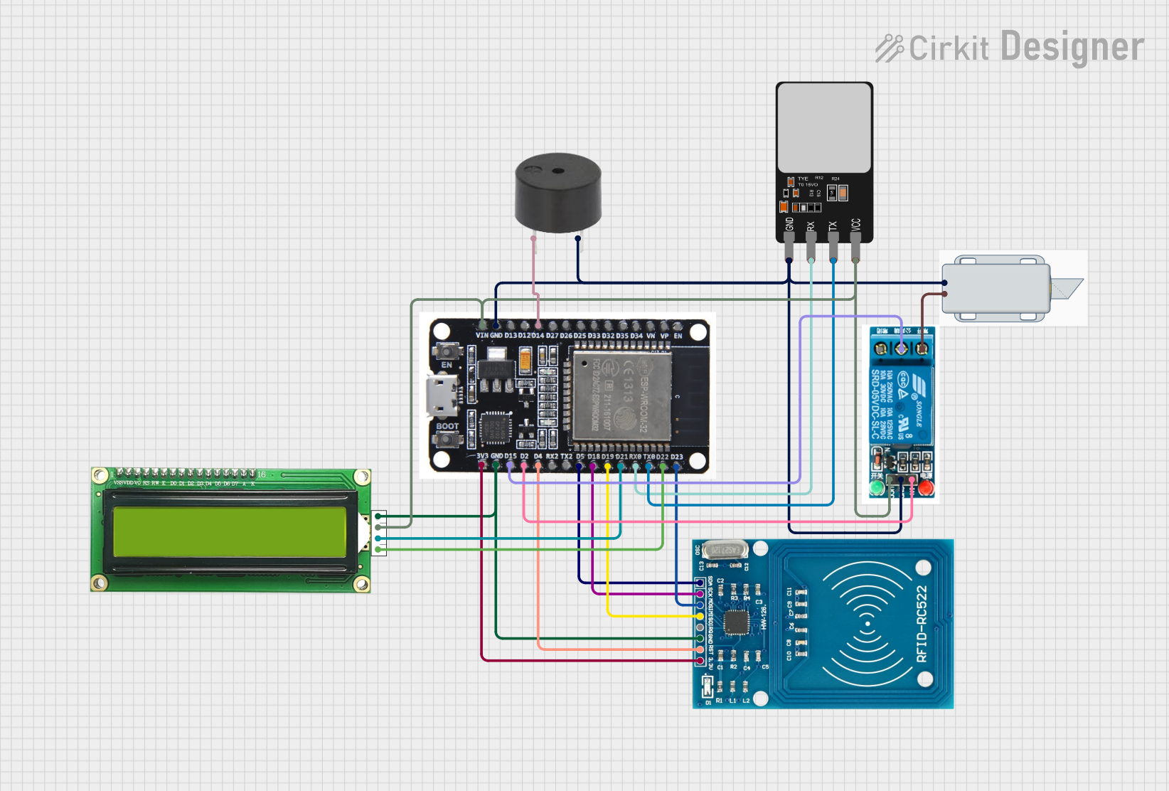
Circuit Documentation
Summary
The circuit in question appears to be designed for a security or access control system, featuring a variety of components including a fingerprint scanner, an RFID reader, a microcontroller (ESP32), a solenoid lock, a buzzer, an LCD display with I2C interface, and a 5V relay. The ESP32 serves as the central processing unit, interfacing with the input devices (fingerprint scanner and RFID reader) and output devices (solenoid lock, buzzer, and LCD display) to control access based on user credentials. The relay is used to control the higher voltage required by the solenoid lock, while the ESP32 operates at 3.3V or 5V logic levels.
Component List
Fingerprint Scanner
- Pins: VCC, TX, RX, GND
- Description: Used to scan and recognize fingerprints for authentication purposes.
12V Solenoid Lock
- Pins: -, +
- Description: An electromechanical lock that is controlled by electrical signals, typically used for securing doors or gates.
Buzzer
- Pins: PIN, GND
- Description: An audible signaling device that can be used for alerts or notifications.
RFID-RC522
- Pins: VCC (3.3V), RST, GND, IRQ, MISO, MOSI, SCK, SDA
- Description: An RFID reader module for reading RFID tags, commonly used for identification and access control.
ESP32
- Pins: EN, VP, VN, D34, D35, D32, D33, D25, D26, D27, D14, D12, D13, GND, VIN, 3V3, D15, D2, D4, RX2, TX2, D5, D18, D19, D21, RX0, TX0, D22, D23, BOOT
- Description: A powerful microcontroller with Wi-Fi and Bluetooth capabilities, used as the main controller in this circuit.
MKE-M07 LCD1602 I2C
- Pins: GND, 5V, SDA, SCL
- Description: An alphanumeric LCD display module with an I2C interface for displaying text or numbers.
5V Relay
- Pins: Normally Open, Common terminal, Normally Closed, In, GND, VCC
- Description: An electrically operated switch that allows the circuit to control devices that operate at higher power levels than the microcontroller can handle directly.
Wiring Details
Fingerprint Scanner
- VCC: Connected to 5V power supply
- TX: Connected to RX0 on ESP32
- RX: Connected to TX0 on ESP32
- GND: Connected to common ground
12V Solenoid Lock
- - (Negative): Connected to common ground
- + (Positive): Connected to Normally Open on 5V relay
Buzzer
- PIN: Connected to D14 on ESP32
- GND: Connected to common ground
RFID-RC522
- VCC (3.3V): Connected to 3V3 on ESP32
- RST: Connected to D4 on ESP32
- GND: Connected to common ground
- MISO: Connected to D19 on ESP32
- MOSI: Connected to D23 on ESP32
- SCK: Connected to D18 on ESP32
- SDA: Connected to D5 on ESP32
ESP32
- GND: Connected to common ground
- VIN: Connected to 5V power supply
- 3V3: Provides 3.3V power to RFID-RC522
- TX0, RX0: Interface with Fingerprint Scanner
- D14: Controls Buzzer
- D4, D19, D23, D18, D5: Interface with RFID-RC522
- D15: Connected to Common terminal on 5V relay
- D2: Controls 5V relay
MKE-M07 LCD1602 I2C
- GND: Connected to common ground
- 5V: Connected to 5V power supply
- SDA: Connected to D21 on ESP32
- SCL: Connected to D22 on ESP32
5V Relay
- VCC: Connected to 5V power supply
- GND: Connected to common ground
- In: Controlled by D2 on ESP32
- Common terminal: Connected to D15 on ESP32
- Normally Open: Connected to + on 12V Solenoid Lock
Documented Code
No code has been provided for the microcontroller (ESP32) in this circuit. The code would typically include initialization and control logic for interfacing with the input devices (fingerprint scanner and RFID reader), driving the output devices (solenoid lock, buzzer, and LCD display), and implementing the access control logic. It would also handle communication protocols such as serial communication with the fingerprint scanner and SPI communication with the RFID reader, as well as I2C communication with the LCD display.