Cirkit Designer
Your all-in-one circuit design IDE
Home /
Project Documentation
Arduino-Controlled Dual DC Motor Driver Circuit
Circuit Documentation
Summary
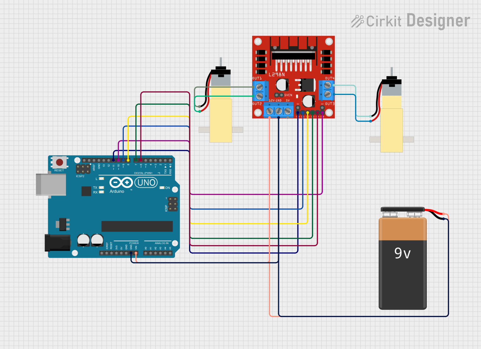
This circuit is designed to control two hobby gearmotors using an Arduino UNO microcontroller and an L298N DC motor driver. The Arduino UNO is responsible for generating control signals that are sent to the L298N driver, which in turn drives the motors. The circuit is powered by a 9V battery, which provides the necessary voltage to the motor driver and the Arduino.
Component List
Arduino UNO
- Microcontroller board based on the ATmega328P
- It has 14 digital input/output pins, 6 analog inputs, a 16 MHz quartz crystal, a USB connection, a power jack, an ICSP header, and a reset button.
L298N DC Motor Driver
- A dual H-bridge motor driver that can drive two DC motors or one stepper motor.
- It has two H-bridge circuits to allow for direction control and speed control via PWM.
Hobby Gearmotor with 48:1 Gearbox (x2)
- A DC motor with a gearbox that provides a 48:1 gear reduction.
- Suitable for driving wheels or other mechanisms in hobby robotics.
9V Battery
- A standard 9V battery used to provide power to the circuit.
Wiring Details
Arduino UNO
- GND connected to the ground of the 9V battery and L298N GND.
- Vin connected to the positive terminal of the 9V battery and L298N 12V.
- D11 connected to L298N ENA for enabling motor A.
- D10 connected to L298N ENB for enabling motor B.
- D9 connected to L298N IN1 for controlling motor A direction.
- D8 connected to L298N IN2 for controlling motor A direction.
- D7 connected to L298N IN3 for controlling motor B direction.
- D6 connected to L298N IN4 for controlling motor B direction.
L298N DC Motor Driver
- GND connected to the ground of the 9V battery and Arduino GND.
- 12V connected to the positive terminal of the 9V battery and Arduino Vin.
- ENA connected to Arduino D11.
- ENB connected to Arduino D10.
- IN1 connected to Arduino D9.
- IN2 connected to Arduino D8.
- IN3 connected to Arduino D7.
- IN4 connected to Arduino D6.
- OUT1 connected to motor A pin 1.
- OUT2 connected to motor A pin 2.
- OUT3 connected to motor B pin 2.
- OUT4 connected to motor B pin 1.
Hobby Gearmotor with 48:1 Gearbox (Motor A)
- pin 1 connected to L298N OUT1.
- pin 2 connected to L298N OUT2.
Hobby Gearmotor with 48:1 Gearbox (Motor B)
- pin 1 connected to L298N OUT4.
- pin 2 connected to L298N OUT3.
9V Battery
- + connected to Arduino Vin and L298N 12V.
- - connected to Arduino GND and L298N GND.
Documented Code
Arduino UNO Code (sketch.ino)
void setup() {
  // Setup code to initialize motor control pins
  pinMode(11, OUTPUT); // ENA
  pinMode(10, OUTPUT); // ENB
  pinMode(9, OUTPUT);  // IN1
  pinMode(8, OUTPUT);  // IN2
  pinMode(7, OUTPUT);  // IN3
  pinMode(6, OUTPUT);  // IN4
}

void loop() {
  // Main code to control motor speed and direction
  // Example: Set motor A to run forward at full speed
  digitalWrite(11, HIGH); // Enable motor A
  digitalWrite(9, HIGH);   // Set IN1 to HIGH
  digitalWrite(8, LOW);    // Set IN2 to LOW
  // Add motor control logic as needed
}
Additional Notes (documentation.txt)
No additional code documentation provided.