
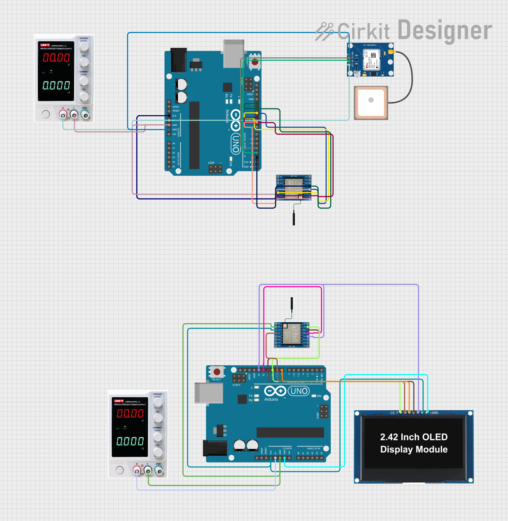
Circuit Documentation
Summary
This circuit involves two Arduino UNO microcontrollers, two LoRa Ra-02 SX1278 modules, a GPS NEO 6M module, an OLED display, and two power supplies. The primary function of this circuit is to read GPS data and transmit it via LoRa, while the second Arduino receives the data and displays it on the OLED screen.
Component List
Arduino UNO
- Description: A microcontroller board based on the ATmega328P.
- Pins: UNUSED, IOREF, Reset, 3.3V, 5V, GND, Vin, A0, A1, A2, A3, A4, A5, SCL, SDA, AREF, D13, D12, D11, D10, D9, D8, D7, D6, D5, D4, D3, D2, D1, D0
LoRa Ra-02 SX1278
- Description: A long-range transceiver module.
- Pins: GND, NSS, MOSI, MISO, SCK, D105, DI04, 3.3V, RST, DI00, DI01, D102, DI03
GPS NEO 6M
- Description: A GPS module for obtaining location data.
- Pins: VCC, RX, TX, GND
Power Supply
- Description: Provides power to the circuit.
- Pins: +, -, GND
OLED Display 2.42
- Description: A 2.42-inch OLED display.
- Pins: GND, VCC, SCK, SDA, RES, DC, CS
Wiring Details
Arduino UNO (1)
- 3.3V: Connected to 3.3V of LoRa Ra-02 SX1278
- 5V: Connected to + of Power Supply, VCC of GPS NEO 6M
- GND: Connected to - of Power Supply, GND of LoRa Ra-02 SX1278, GND of GPS NEO 6M
- D13: Connected to SCK of LoRa Ra-02 SX1278
- D12: Connected to MISO of LoRa Ra-02 SX1278
- D11: Connected to MOSI of LoRa Ra-02 SX1278
- D10: Connected to NSS of LoRa Ra-02 SX1278
- D9: Connected to RST of LoRa Ra-02 SX1278
- D4: Connected to TX of GPS NEO 6M
- D3: Connected to RX of GPS NEO 6M
- D2: Connected to DI00 of LoRa Ra-02 SX1278
LoRa Ra-02 SX1278 (1)
- 3.3V: Connected to 3.3V of Arduino UNO
- GND: Connected to GND of Arduino UNO, - of Power Supply
- SCK: Connected to D13 of Arduino UNO
- MISO: Connected to D12 of Arduino UNO
- MOSI: Connected to D11 of Arduino UNO
- NSS: Connected to D10 of Arduino UNO
- RST: Connected to D9 of Arduino UNO
- DI00: Connected to D2 of Arduino UNO
GPS NEO 6M
- VCC: Connected to 5V of Arduino UNO
- RX: Connected to D3 of Arduino UNO
- TX: Connected to D4 of Arduino UNO
- GND: Connected to GND of Arduino UNO
Power Supply (1)
- +: Connected to 5V of Arduino UNO
- -: Connected to GND of Arduino UNO, GND of LoRa Ra-02 SX1278
Arduino UNO (2)
- 3.3V: Connected to 3.3V of LoRa Ra-02 SX1278, VCC of OLED Display
- 5V: Connected to + of Power Supply
- GND: Connected to - of Power Supply, GND of LoRa Ra-02 SX1278, GND of OLED Display
- D13: Connected to SCK of LoRa Ra-02 SX1278, SCK of OLED Display
- D12: Connected to MISO of LoRa Ra-02 SX1278
- D11: Connected to MOSI of LoRa Ra-02 SX1278, SDA of OLED Display
- D10: Connected to NSS of LoRa Ra-02 SX1278, CS of OLED Display
- D9: Connected to RST of LoRa Ra-02 SX1278, DC of OLED Display
- D8: Connected to RES of OLED Display
LoRa Ra-02 SX1278 (2)
- 3.3V: Connected to 3.3V of Arduino UNO
- GND: Connected to GND of Arduino UNO, - of Power Supply
- SCK: Connected to D13 of Arduino UNO, SCK of OLED Display
- MISO: Connected to D12 of Arduino UNO
- MOSI: Connected to D11 of Arduino UNO, SDA of OLED Display
- NSS: Connected to D10 of Arduino UNO, CS of OLED Display
- RST: Connected to D9 of Arduino UNO, DC of OLED Display
OLED Display 2.42
- VCC: Connected to 3.3V of Arduino UNO
- GND: Connected to GND of Arduino UNO
- SCK: Connected to D13 of Arduino UNO, SCK of LoRa Ra-02 SX1278
- SDA: Connected to D11 of Arduino UNO, MOSI of LoRa Ra-02 SX1278
- RES: Connected to D8 of Arduino UNO
- DC: Connected to D9 of Arduino UNO, RST of LoRa Ra-02 SX1278
- CS: Connected to D10 of Arduino UNO, NSS of LoRa Ra-02 SX1278
Power Supply (2)
- +: Connected to 5V of Arduino UNO
- -: Connected to GND of Arduino UNO, GND of LoRa Ra-02 SX1278
Documented Code
Arduino UNO (1) Code
#include <SPI.h>
#include <LoRa.h>
#include <SoftwareSerial.h>

// GPS Module Pins
#define RXPin 4
#define TXPin 3

SoftwareSerial GPS(RXPin, TXPin);

void setup() {
  Serial.begin(9600);
  GPS.begin(9600);

  if (!LoRa.begin(433E6)) {
    Serial.println("Starting LoRa failed!");
    while (1);
  }
}

void loop() {
  // Read data from the GPS module
  if (GPS.available()) {
    String gpsData = GPS.readStringUntil('\n');
    Serial.println(gpsData);

    // Send GPS data via LoRa
    LoRa.beginPacket();
    LoRa.print("SOS, Location: ");
    LoRa.print(gpsData);
    LoRa.endPacket();

    delay(10000); // Wait 10 seconds before sending the next message
  }
}
Arduino UNO (2) Code
#include <SPI.h>
#include <LoRa.h>
#include <Adafruit_GFX.h>
#include <Adafruit_SSD1306.h>

// OLED Display Pins
#define OLED_CS     10
#define OLED_DC     9
#define OLED_RESET  8

Adafruit_SSD1306 display(128, 64, &SPI, OLED_CS, OLED_DC, OLED_RESET);

void setup() {
  Serial.begin(9600);

  // Initialize OLED display
  if (!display.begin(SSD1306_SWITCHCAPVCC, 0x3C)) {
    Serial.println(F("SSD1306 allocation failed"));
    for (;;);
  }
  display.display();
  delay(2000);
  display.clearDisplay();

  if (!LoRa.begin(433E6)) {
    Serial.println("Starting LoRa failed!");
    while (1);
  }
}

void loop() {
  // Check for incoming LoRa packets
  int packetSize = LoRa.parsePacket();
  if (packetSize) {
    String incoming = "";
    while (LoRa.available()) {
      incoming += (char)LoRa.read();
    }
    Serial.println(incoming);

    // Display received message on OLED
    display.clearDisplay();
    display.setCursor(0, 0);
    display.println("Received message:");
    display.println(incoming);
    display.display();
  }
}