
Arduino UNO Controlled Security System with GSM Module and Environmental Sensing
View and Edit Project In Cirkit Designer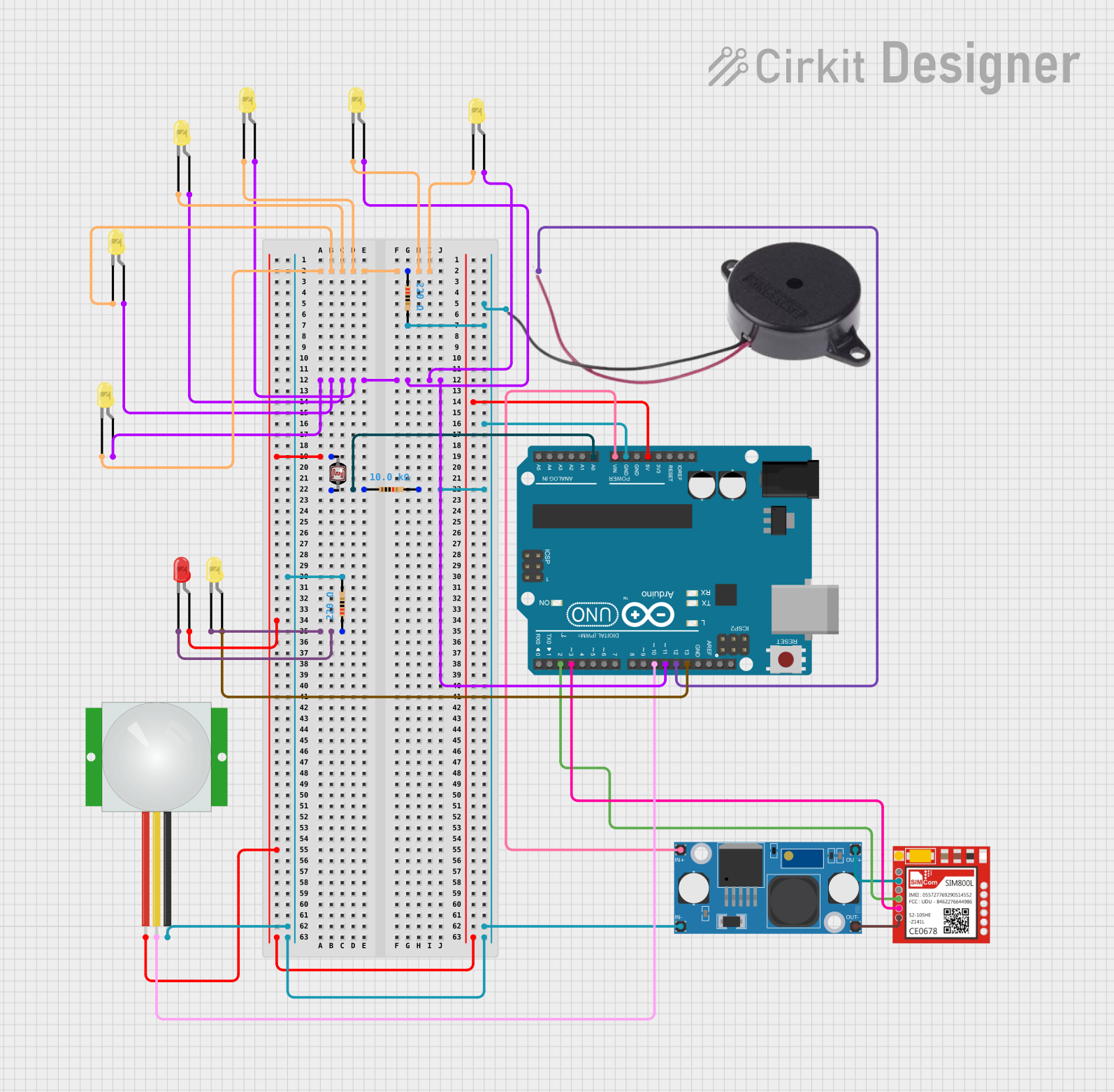
Circuit Documentation
Summary
This circuit integrates various components including an Arduino UNO microcontroller, a SIM800L GSM module, multiple LEDs, a PIR sensor, a photocell (LDR), a buzzer, resistors, and an LM2596 step-down module. The Arduino UNO serves as the central processing unit, interfacing with sensors and controlling outputs like LEDs and the buzzer. The SIM800L module provides GSM functionality, allowing the circuit to communicate over cellular networks. The LM2596 module steps down the input voltage to a lower level suitable for the SIM800L and other components. The PIR sensor detects motion, and the photocell senses light levels. The LEDs provide visual indications, and the buzzer can generate audible alerts. Resistors are used for current limiting and voltage division.
Component List
- Arduino UNO: A microcontroller board based on the ATmega328P, featuring digital and analog I/O pins.
- Sim800l: A GSM/GPRS module that allows cellular network communication.
- LED (yellow): Yellow light-emitting diodes used for indication purposes.
- LED (red): A red light-emitting diode used for indication purposes.
- LM2596 Step Down Module: A voltage regulator that steps down an input voltage to a lower output voltage.
- PIR sensor: A passive infrared sensor that detects motion by measuring changes in the infrared levels emitted by surrounding objects.
- Photocell (LDR): A light-dependent resistor whose resistance changes based on light intensity.
- Buzzer: An electronic component that produces sound.
- Resistor (10k Ohms): A resistor with a resistance of 10,000 Ohms, often used for voltage division or current limiting.
- Resistor (220 Ohms): A resistor with a resistance of 220 Ohms, typically used to limit current to LEDs.
Wiring Details
Arduino UNO
- GND: Connected to the negative side of the buzzer, negative side of the LM2596 module, and ground pins of the PIR sensor and resistors.
- 5V: Powers the PIR sensor and the photocell (LDR).
- Vin: Input voltage for the LM2596 module.
- A0: Reads the voltage across the photocell (LDR) and a 10k Ohm resistor.
- D2: Receives serial data (RXD) from the SIM800L module.
- D3: Transmits serial data (TXD) to the SIM800L module.
- D10: Receives the signal from the PIR sensor.
- D11: Controls the anodes of multiple yellow LEDs.
- D12: Powers the positive side of the buzzer.
- D13: Controls the anode of a yellow LED.
Sim800l
- VCC: Powered by the LM2596 module's output.
- RXD: Connected to D2 on the Arduino UNO.
- TXD: Connected to D3 on the Arduino UNO.
- GND: Connected to the ground side of the LM2596 module's output.
LEDs (yellow and red)
- Cathode (yellow): Connected to a 220 Ohm resistor, which is then connected to the ground.
- Anode (yellow): Connected to D11 on the Arduino UNO (multiple LEDs) or D13 for a single LED.
- Cathode (red): Connected to a 220 Ohm resistor, which is then connected to the ground.
- Anode (red): Connected to the 5V output from the Arduino UNO.
LM2596 Step Down Module
- IN+: Connected to Vin on the Arduino UNO.
- IN-: Connected to GND on the Arduino UNO.
- OUT+: Powers the VCC of the SIM800L module.
- OUT-: Connected to the GND of the SIM800L module.
PIR sensor
- VDD: Powered by the 5V output from the Arduino UNO.
- SIG: Signal connected to D10 on the Arduino UNO.
- GND: Connected to the ground on the Arduino UNO.
Photocell (LDR)
- Pin 0: Connected to the 5V output from the Arduino UNO.
- Pin 1: Connected to A0 on the Arduino UNO through a 10k Ohm resistor.
Buzzer
- POSITIVE: Connected to D12 on the Arduino UNO.
- NEGATIVE: Connected to the ground on the Arduino UNO.
Resistors
- 10k Ohms: One side connected to the photocell (LDR) and A0 on the Arduino UNO, the other side to the ground.
- 220 Ohms: Connected between the cathodes of the LEDs and the ground.
Documented Code
void setup() {
  // put your setup code here, to run once:

}

void loop() {
  // put your main code here, to run repeatedly:

}
The provided code is a template for the Arduino UNO with empty setup() and loop() functions. The setup() function is intended for initialization code that runs once when the microcontroller is powered on or reset. The loop() function contains the main logic of the program, which runs repeatedly as long as the microcontroller is powered.
Further implementation details would be required to control the components as per the wiring details provided. This would include configuring the I/O pins, setting up serial communication with the SIM800L module, reading sensor inputs, and controlling the outputs to the LEDs and buzzer.