Cirkit Designer
Your all-in-one circuit design IDE
Home /
Project Documentation
Arduino UNO-Based Health Monitoring System with Bluetooth and WiFi Connectivity
Circuit Documentation
Summary of the Circuit
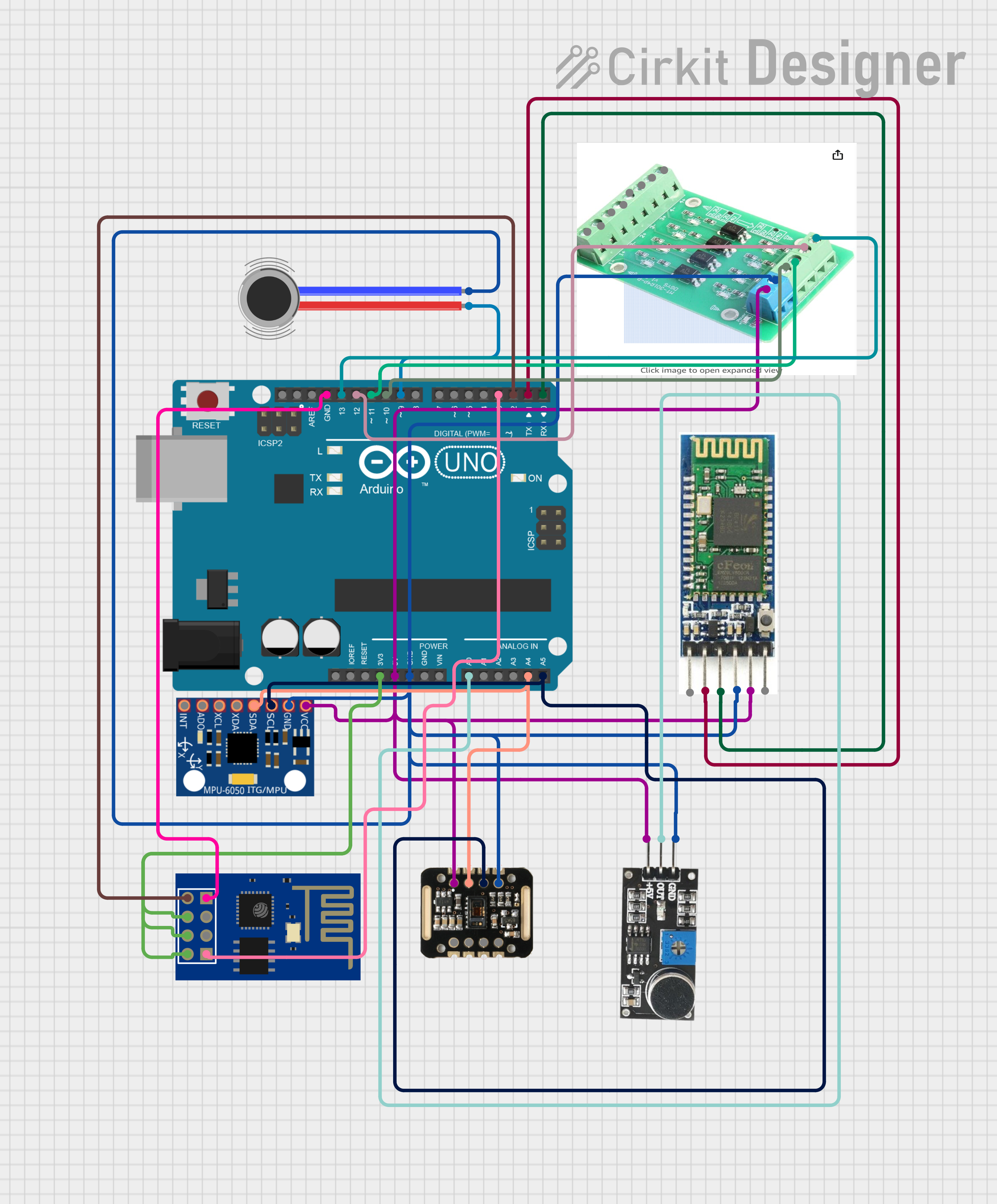
This circuit integrates a variety of components including an Arduino UNO microcontroller, a Bluetooth module, a MAX30100 pulse oximeter and heart-rate sensor, an MPU-6050 accelerometer and gyroscope, a sound sensor, a vibration motor, an optocoupler, and an ESP8266 ESP-01 WiFi module. The Arduino UNO serves as the central processing unit, interfacing with the sensors and communication modules to perform data acquisition, processing, and wireless communication tasks.
Component List
Arduino UNO
- Microcontroller board based on the ATmega328P
- Features digital I/O pins, analog input pins, and various power outputs
Bluetooth Module
- Wireless communication module for short-range data exchange
- Operates with standard Bluetooth protocol for connectivity with other Bluetooth devices
MAX30100
- Integrated pulse oximetry and heart-rate sensor module
- Utilizes I2C communication for interfacing with the microcontroller
MPU-6050
- Motion tracking device with a 3-axis gyroscope and a 3-axis accelerometer
- Communicates with the microcontroller via I2C interface
Sound Sensor
- Detects sound intensity levels and provides an analog output signal
Vibration Motor
- Provides haptic feedback or vibration alerts
Optocoupler
- Electrically isolates input from output using light transmission
- Protects low voltage side of the circuit from high voltage spikes
ESP8266 ESP-01 WiFi Module
- WiFi module capable of connecting the circuit to a wireless network
- Enables IoT capabilities for the circuit
Wiring Details
Arduino UNO
3.3Vconnected to ESP8266 ESP-01 WiFi Module (VCC, CH_PD, RST)5Vconnected to Bluetooth Module (VCC), MAX30100 (VIN), Sound Sensor (5V +), MPU-6050 (VCC), Optocoupler (VCC)GNDconnected to Bluetooth Module (GND), MAX30100 (GND), Sound Sensor (GND), MPU-6050 (GND), Vibration Motor (NEG), Optocoupler (Ground), ESP8266 ESP-01 WiFi Module (GND)A0connected to Sound Sensor (OUT)A4(SDA) connected to MAX30100 (SDA), MPU-6050 (SDA)A5(SCL) connected to MAX30100 (SCL), MPU-6050 (SCL)D2connected to ESP8266 ESP-01 WiFi Module (TXD)D3connected to ESP8266 ESP-01 WiFi Module (RXD)D9connected to Vibration Motor (POS)D10connected to Optocoupler (o1)D11connected to Optocoupler (o2)D12connected to Optocoupler (o3)D13connected to Optocoupler (o4)D0(RX) connected to Bluetooth Module (TXD)D1(TX) connected to Bluetooth Module (RXD)
Bluetooth Module
VCCconnected to Arduino UNO (5V)GNDconnected to Arduino UNO (GND)TXDconnected to Arduino UNO (D0)RXDconnected to Arduino UNO (D1)
MAX30100
VINconnected to Arduino UNO (5V)GNDconnected to Arduino UNO (GND)SDAconnected to Arduino UNO (A4)SCLconnected to Arduino UNO (A5)
MPU-6050
VCCconnected to Arduino UNO (5V)GNDconnected to Arduino UNO (GND)SDAconnected to Arduino UNO (A4)SCLconnected to Arduino UNO (A5)
Sound Sensor
5V +connected to Arduino UNO (5V)GNDconnected to Arduino UNO (GND)OUTconnected to Arduino UNO (A0)
Vibration Motor
POSconnected to Arduino UNO (D9)NEGconnected to Arduino UNO (GND)
Optocoupler
VCCconnected to Arduino UNO (5V)Groundconnected to Arduino UNO (GND)o1connected to Arduino UNO (D10)o2connected to Arduino UNO (D11)o3connected to Arduino UNO (D12)o4connected to Arduino UNO (D13)
ESP8266 ESP-01 WiFi Module
VCC,CH_PD,RSTconnected to Arduino UNO (3.3V)GNDconnected to Arduino UNO (GND)TXDconnected to Arduino UNO (D2)RXDconnected to Arduino UNO (D3)
Documented Code
Arduino UNO Code (sketch.ino)
void setup() {
  // put your setup code here, to run once:

}

void loop() {
  // put your main code here, to run repeatedly:

}
Note: The provided code is a template and does not contain any functional implementation. It is expected that the user will fill in the setup and loop functions with the necessary code to operate the circuit as intended.