
Arduino and ESP32-Based Smart Automation System with RFID Access Control
View and Edit Project In Cirkit Designer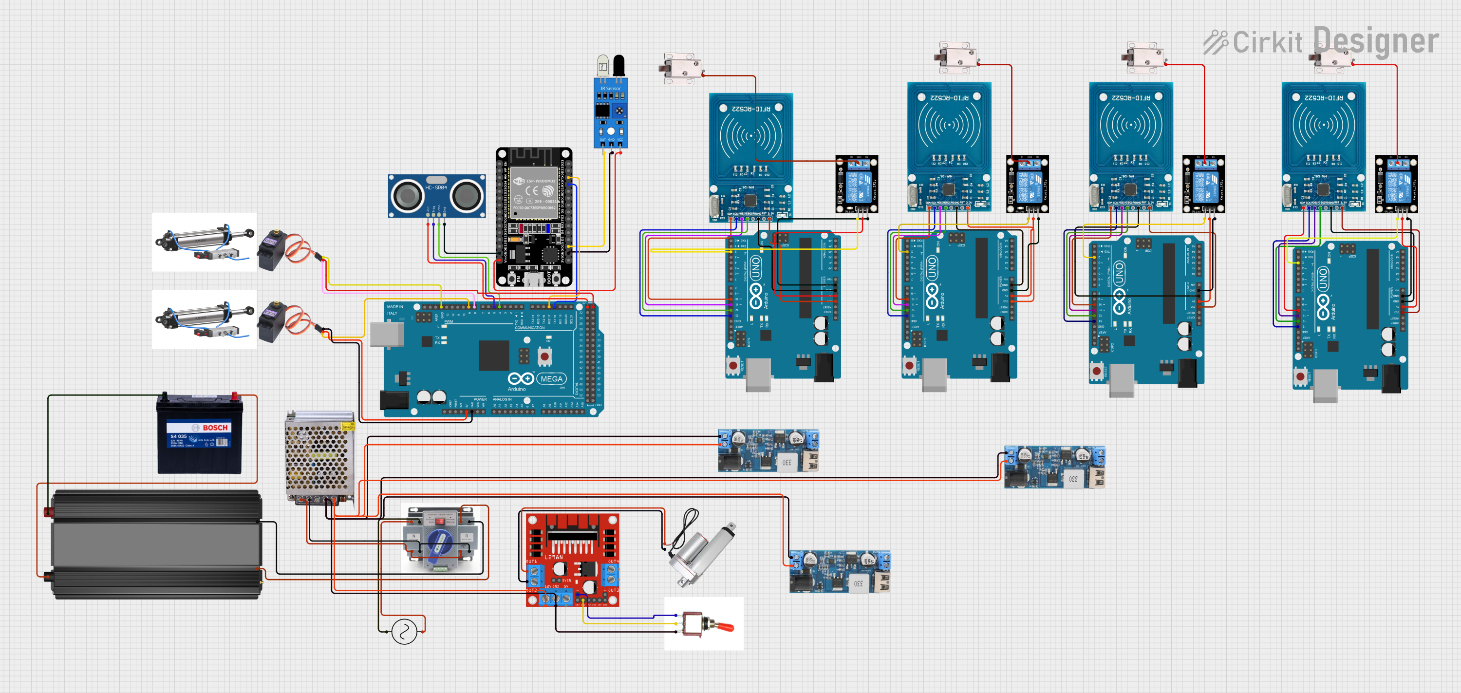
Circuit Documentation
Summary
This document provides a detailed overview of a complex circuit that includes multiple microcontrollers, relay modules, sensors, actuators, power supply components, and interfacing modules. The circuit is designed to control various devices and sensors, including linear actuators, servo motors, an ultrasonic sensor, RFID modules, and solenoid locks. Communication between components is facilitated through wired connections, and the system is powered by a combination of a 12V power supply and a 12V battery. The circuit's functionality is controlled by Arduino UNO and Mega microcontrollers, as well as an ESP32 module.
Component List
- ATS (Automatic Transfer Switch): Used to switch power sources between mains and a backup.
- Arduino UNO: A microcontroller board based on the ATmega328P, used for controlling various peripherals and sensors.
- Arduino Mega 2560: A microcontroller board based on the ATmega2560, with additional I/O pins and memory, used for more complex control tasks.
- KY-019 Relay Module 1 Channel: Used to control high power devices with a low power signal.
- POWER SUPPLY 12V 5AMP: Provides a stable 12V DC output for powering the circuit.
- 12V 200Ah Battery: Acts as a backup power source for the circuit.
- Power Inverter: Converts DC power from the battery to AC power.
- Ac Supply: The main AC power source for the circuit.
- Toggle Switch: A manual switch used to control the flow of electricity.
- Linear Actuator: An electric motor that creates motion in a straight line.
- RFID-RC522: An RFID reader module for reading RFID tags.
- IR Sensor: Detects infrared light to sense the presence or absence of objects.
- HC-SR04 Ultrasonic Sensor: Measures distance by emitting ultrasonic waves and timing their reflection.
- ESP32 (30 pin): A microcontroller with Wi-Fi and Bluetooth capabilities for wireless communication.
- MG996R: A high-torque servo motor for precise angular motion.
- Pneumatic Cylinder: A cylinder driven by compressed air to create linear motion.
- 12V Solenoid Lock: An electromagnetic lock powered by 12V for security applications.
- 12v to 5v Step Down Power Converter: Converts 12V DC to 5V DC to power 5V devices.
- L298N DC Motor Driver: Controls the direction and speed of DC motors.
Wiring Details
ATS (Automatic Transfer Switch)
- Connected to the AC Supply and Power Supply 12V 5AMP to switch between power sources.
Arduino UNO
- Multiple instances, each controlling different peripherals like RFID-RC522 modules and KY-019 Relay modules.
- Powered by 5V from the 12v to 5v Step Down Power Converter or the Arduino Mega 2560.
Arduino Mega 2560
- Controls MG996R servo motors, the HC-SR04 Ultrasonic Sensor, and communicates with the ESP32 module.
- Powered by the 12V Power Supply.
KY-019 Relay Module 1 Channel
- Controlled by Arduino UNO boards to switch 12V solenoid locks and other high-power devices.
POWER SUPPLY 12V 5AMP
- Powers the L298N DC motor driver and provides 12V to the step-down converters.
12V 200Ah Battery
- Backup power source connected to the Power Inverter.
Power Inverter
- Converts DC from the battery to AC, connected to the ATS.
Ac Supply
- Main AC power source connected to the ATS.
Toggle Switch
- Controls the L298N DC motor driver.
Linear Actuator
- Controlled by the L298N DC motor driver to create linear motion.
RFID-RC522
- Multiple instances connected to different Arduino UNO boards for RFID tag reading.
IR Sensor
- Connected to the ESP32 for object detection.
HC-SR04 Ultrasonic Sensor
- Connected to the Arduino Mega 2560 for distance measurement.
ESP32 (30 pin)
- Communicates with the Arduino Mega 2560 and controls the IR sensor.
MG996R
- Servo motors controlled by the Arduino Mega 2560 for precise movements.
12V Solenoid Lock
- Multiple instances controlled by KY-019 Relay modules for locking mechanisms.
12v to 5v Step Down Power Converter
- Converts 12V to 5V to power Arduino UNO boards and other 5V peripherals.
L298N DC Motor Driver
- Controls the Linear Actuator and is powered by the 12V Power Supply.
Documented Code
Arduino UNO (Instance 1)
void setup() {
  // put your setup code here, to run once:

}

void loop() {
  // put your main code here, to run repeatedly:

}
Arduino UNO (Instance 2)
void setup() {
  // put your setup code here, to run once:

}

void loop() {
  // put your main code here, to run repeatedly:

}
Arduino Mega 2560
void setup() {
  // put your setup code here, to run once:

}

void loop() {
  // put your main code here, to run repeatedly:

}
ESP32 (30 pin)
void setup() {
  // put your setup code here, to run once:

}

void loop() {
  // put your main code here, to run repeatedly:

}
(Note: The provided code for each microcontroller is a template and does not contain specific functionality. The actual implementation will depend on the desired behavior of the circuit.)