Arduino-Controlled Motor with Proximity Sensor Feedback and LCD Interface
Circuit Documentation
Summary
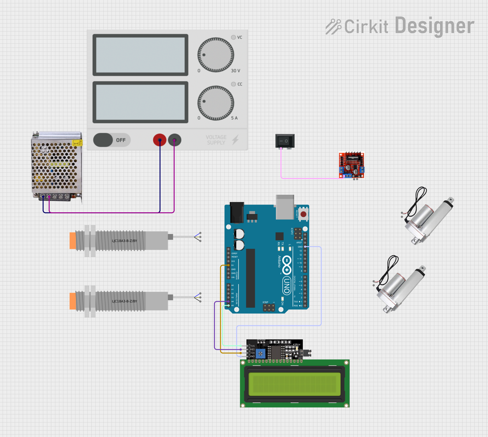
This circuit is designed to control a motor using an Arduino UNO microcontroller in conjunction with a L298N Motor Driver. The system's operation is influenced by the state of a rocker switch and two capacitive proximity sensors. An LCD display is included for user interface or status display purposes. The power supply is managed through a 12V 5A power supply unit, which is connected to a secondary power supply module and controlled by a rocker switch. The circuit is designed to respond to the proximity sensors and control the direction of the motor accordingly.
Component List
Arduino UNO
- Microcontroller board based on the ATmega328P.
- It has 14 digital input/output pins, 6 analog inputs, a 16 MHz quartz crystal, a USB connection, a power jack, an ICSP header, and a reset button.
LJC18A3-B-Z/BY Capacitive Proximity Sensor
- A sensor that can detect the presence or absence of an object capacitively.
- It has three pins: VO (Voltage Output), VI (Voltage Input), and SIG (Signal).
POWER SUPPLY 12V 5AMP
- A power supply unit that converts 220V AC to 12V-24V DC.
- It has three output pins: GND (Ground), GND (DC), and 12V-24V Output (DC).
L298N Motor Driver Controller Board Module
- A motor driver module that can control up to two DC motors or one stepper motor.
- It has multiple pins for motor outputs, power inputs, and control inputs.
Power Supply
- A generic power supply module.
- It has two pins: + (Positive) and - (Negative).
Rocker Switch (SPST)
- A single-pole single-throw (SPST) switch.
- It has two pins for connecting and disconnecting a circuit.
LCD Display 16x4 I2C
- A 16x4 character LCD display with an I2C interface.
- It has four pins: SCL (Serial Clock Line), SDA (Serial Data Line), VCC (Power), and GND (Ground).
Linear Actuator
- A device that creates motion in a straight line.
- It has two pins: + (Positive) and - (Negative).
Wiring Details
Arduino UNO
5Vto LCD Display 16x4 I2CVCCA4to LCD Display 16x4 I2CSDAA5to LCD Display 16x4 I2CSCLGNDto LCD Display 16x4 I2CGND
LCD Display 16x4 I2C
VCCto Arduino UNO5VSDAto Arduino UNOA4SCLto Arduino UNOA5GNDto Arduino UNOGND
Power Supply
+to POWER SUPPLY 12V 5AMP220V Positive Pole (AC)-to POWER SUPPLY 12V 5AMP220V Negative Pole (AC)
L298N Motor Driver Controller Board Module
+12v Powerto Rocker Switch (SPST)2
Documented Code
// Pin definitions
const int rockerSwitchPin = 5; // Pin connected to the Rocker Switch
const int motorInput1 = 3;     // Pin connected to Input 1 of the L298N Motor Driver
const int motorInput2 = 4;     // Pin connected to Input 2 of the L298N Motor Driver
const int proximitySensor1 = 2; // Pin connected to SIG (BLK) of the first Capacitive Proximity Sensor
const int proximitySensor2 = 6; // Pin connected to SIG (BLK) of the second Capacitive Proximity Sensor

void setup() {
  // Initialize the pins
  pinMode(rockerSwitchPin, INPUT);
  pinMode(motorInput1, OUTPUT);
  pinMode(motorInput2, OUTPUT);
  pinMode(proximitySensor1, INPUT);
  pinMode(proximitySensor2, INPUT);

  // Start with the motor off
  digitalWrite(motorInput1, LOW);
  digitalWrite(motorInput2, LOW);
}

void loop() {
  // Read the state of the Rocker Switch
  int switchState = digitalRead(rockerSwitchPin);

  // Read the state of the proximity sensors
  int sensor1State = digitalRead(proximitySensor1);
  int sensor2State = digitalRead(proximitySensor2);

  // If the Rocker Switch is on, control the motor based on the proximity sensors
  if (switchState == HIGH) {
    if (sensor1State == HIGH) {
      // If the first sensor is triggered, rotate the motor in one direction
      digitalWrite(motorInput1, HIGH);
      digitalWrite(motorInput2, LOW);
    } else if (sensor2State == HIGH) {
      // If the second sensor is triggered, rotate the motor in the opposite direction
      digitalWrite(motorInput1, LOW);
      digitalWrite(motorInput2, HIGH);
    } else {
      // If no sensor is triggered, stop the motor
      digitalWrite(motorInput1, LOW);
      digitalWrite(motorInput2, LOW);
    }
  } else {
    // If the Rocker Switch is off, stop the motor
    digitalWrite(motorInput1, LOW);
    digitalWrite(motorInput2, LOW);
  }

  // Add a small delay to debounce the switch and sensors
  delay(50);
}
This code is designed to run on the Arduino UNO microcontroller. It initializes the pins connected to the rocker switch, motor driver inputs, and proximity sensors. In the main loop, it reads the state of the rocker switch and proximity sensors to control the motor's direction. If the rocker switch is turned on, the motor's direction is determined by which proximity sensor is triggered. If neither sensor is triggered or the rocker switch is off, the motor is stopped. A small delay is added to debounce the inputs.